 ALLPCB


Electromagnetic Compatibility (EMC) testing covers a wide range of standards and procedures. Key test items include:
- Conducted Emissions (CE)
- Radiated Emissions (RE)
- Harmonics
- Voltage Fluctuations and Flicker
- Electrostatic Discharge (ESD)
- Electrical Fast Transient (EFT) / Burst
- Conducted Immunity
- Radiated Immunity
- Surge
- Voltage Dips, Short Interruptions, and Voltage Variations
- Power Frequency Magnetic Field
This article will focus on Conducted Emissions (CE).
EMC studies how various electrical devices can coexist within a limited space, time, and frequency spectrum. The core of EMC involves three elements: the interference source, the sensitive device (victim), and the coupling path. When troubleshooting EMC issues, the analysis often focuses on the return or discharge paths of common-mode currents. For example, ESD contains both DC and AC components, requiring consideration of both differential-mode and common-mode interference.
What Are Conducted Emissions?
Conducted emissions are unwanted higher-frequency signals generated by a device that propagate along its power lines. Covering a frequency range of 150 kHz to 30 MHz, these emissions can interfere with other equipment connected to the same power grid.
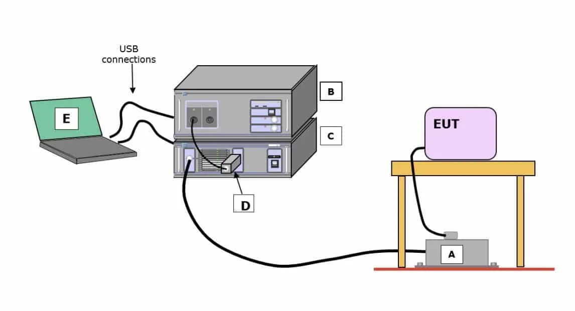
A key component in this test is the Line Impedance Stabilization Network (LISN), which serves several purposes:
- Provides a fixed, stable input impedance for the device under test (DUT) at the line and neutral terminals.
- Isolates the DUT from external noise on the power line.
- Couples the conducted noise current to an EMI receiver (a type of spectrum analyzer) and converts it to a voltage for measurement.
Causes of CE Test Failures
Several factors can cause a device to fail a conducted emissions test:
- Power Circuits: AC-DC and DC-DC converters operate in a pulsed state, generating strong differential-mode and common-mode noise. Battery charging circuits are a common example of DC-DC converters that can be a source of interference.
- Digital Circuits: The transient switching states in digital circuits can produce noise currents. While decoupling capacitors on the PCB help, some transient currents can still propagate onto the power lines.
- Internal Coupling: Internal PCBs and cables act as radiating sources. This radiated energy can couple onto power lines and the power supply circuitry itself, manifesting as conducted emissions.
Solutions for Mitigating Conducted Emissions
1. Input Filtering
The primary method for resolving conducted emissions issues is to add a filter at the power input, either through a dedicated power line filter module or by adding common-mode and differential-mode filtering components to the power supply board. A typical filter uses X capacitors, Y capacitors, common-mode chokes, and sometimes PE (protective earth) inductors. The value of Y capacitors presents a trade-off: larger capacitance improves filtering but can increase leakage current, so a balance must be found while also considering board space and cost.
2. Grounding Adjustments
The grounding method for primary-side heatsinks and PFC inductor cores can have a significant impact on test results. Experimenting with different grounding points and techniques for these components is a valuable troubleshooting step.
3. Proper Filter Installation
Correctly installing the power line filter is critical for its effectiveness.


