 ALLPCB


In the world of electronics, managing heat is critical to ensuring the reliability and performance of your printed circuit boards (PCBs). Poor thermal management can lead to component failure, reduced lifespan, and even safety hazards. So, how do you design a PCB that stays cool under pressure while adhering to standard dimensions? This blog post dives deep into PCB thermal design, PCB heat dissipation methods, component placement guidelines, PCB material selection, and standard PCB dimensions thermal properties to help you create efficient and durable designs. Whether you're an engineer or a hobbyist, you'll find actionable tips to keep your components cool and your projects running smoothly.
Why Thermal Management Matters in PCB Design
Heat is the silent enemy of electronic devices. When components on a PCB generate excessive heat, it can cause thermal stress, degrade performance, and shorten the lifespan of the board. Effective thermal management ensures that heat is dissipated efficiently, maintaining optimal operating temperatures. This is especially important in high-power applications like power supplies, LED lighting, and automotive electronics where heat generation is significant.
Beyond performance, thermal management also ties into the physical constraints of standard PCB dimensions. Boards often need to fit into specific enclosures or systems, meaning you must balance size with heat dissipation capabilities. Let’s explore how to achieve this balance through design strategies and material choices.
Understanding Standard PCB Dimensions and Their Thermal Implications
Standard PCB dimensions are often dictated by industry norms and the specific requirements of the application. A common thickness for PCBs is around 1.57 mm (0.062 inches), which is widely used due to its balance of rigidity and flexibility. However, thickness impacts thermal performance. Thinner boards may struggle to dissipate heat effectively, while thicker boards can handle more thermal load but may increase manufacturing costs.
The size of the PCB also plays a role in thermal management. Larger boards have more surface area for heat dissipation, but they may not fit into compact devices. Smaller boards, while space-efficient, can suffer from concentrated heat buildup if not designed carefully. For instance, a board with dimensions of 100 mm x 50 mm might be ideal for a handheld device, but without proper heat dissipation methods, components like power transistors could overheat.
When designing within these constraints, consider how standard PCB dimensions thermal properties affect heat flow. Copper layers, for example, act as heat spreaders. A 4-layer board with internal copper planes can reduce thermal resistance by up to 30% compared to a 2-layer board, based on typical industry data. Keep these properties in mind as you plan your layout and select materials.
Key Strategies for PCB Thermal Design
Effective PCB thermal design starts with understanding how heat moves through your board and components. Here are some proven strategies to keep temperatures under control:
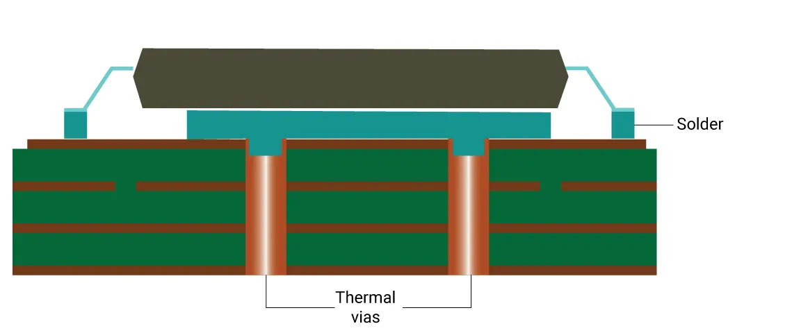
1. Use Thermal Vias for Heat Transfer
Thermal vias are small holes filled with conductive material, typically copper, that transfer heat from one layer of the PCB to another. Placing thermal vias near high-heat components like power ICs can reduce hotspot temperatures by channeling heat to a larger copper plane or external heatsink. For example, a grid of 0.3 mm vias spaced 1.2 mm apart under a component can lower its junction temperature by up to 10°C, depending on the design.
2. Optimize Copper Planes for Heat Spreading
Copper is an excellent conductor of heat, with a thermal conductivity of about 400 W/m·K. By dedicating large areas of copper on your PCB layers to act as heat spreaders, you can distribute heat more evenly across the board. On a 4-layer PCB, for instance, allocating 5,000 mm2 of copper on an internal layer near a heat source can significantly reduce thermal resistance.
3. Incorporate Heatsinks and Thermal Pads
For components that generate substantial heat, such as voltage regulators, attaching a heatsink can be a game-changer. Heatsinks increase the surface area available for heat dissipation into the surrounding air. Thermal pads, with conductivities often ranging from 1 to 5 W/m·K, provide a conductive path between the component and the heatsink, enhancing heat transfer.
PCB Heat Dissipation Methods: Practical Techniques
Implementing effective PCB heat dissipation methods requires a combination of design techniques and hardware solutions. Let’s break down some practical approaches:
1. Natural Convection Cooling
Natural convection relies on the movement of air around the PCB to carry heat away. To maximize this effect, orient components vertically to encourage airflow and avoid placing heat-sensitive parts near high-power components. Ensure there’s at least 10-15 mm of clearance around the board in an enclosure for air circulation.
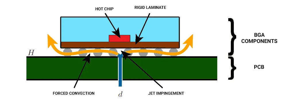
2. Forced Air Cooling
In high-power applications, natural convection may not be enough. Adding a fan to create forced air cooling can significantly lower temperatures. For instance, a small 12V fan providing 20 cubic feet per minute (CFM) of airflow can reduce PCB temperatures by 15-20°C in a confined space.
3. Active Cooling with Heat Pipes
For advanced designs, heat pipes offer a high-efficiency solution. These devices use a liquid-to-vapor phase change to transfer heat away from critical areas. While more expensive, they can be critical for compact, high-performance boards where space for traditional heatsinks is limited.
Component Placement Guidelines for Optimal Heat Distribution
Where you place components on a PCB can make or break your thermal management strategy. Follow these component placement guidelines to minimize heat buildup:
1. Space Out High-Heat Components
Distribute components that generate significant heat, like power transistors or microcontrollers, across the board rather than clustering them in one area. This prevents localized hotspots and allows heat to dissipate more evenly. A spacing of at least 5-10 mm between high-power components is a good starting point.
2. Place Heat-Sensitive Components Strategically
Keep heat-sensitive components, such as capacitors or sensors, away from heat sources. Position them in areas with better airflow or closer to the edges of the board where heat can escape more easily.
3. Align Components with Airflow
If your design includes forced air cooling, align taller components like inductors or connectors in the direction of airflow to minimize turbulence. This ensures that air can flow smoothly over the board, carrying heat away efficiently.

PCB Material Selection: Choosing the Right Foundation for Thermal Performance
The materials you choose for your PCB have a direct impact on its thermal performance. Here’s how PCB material selection can influence heat dissipation:
1. Substrate Materials
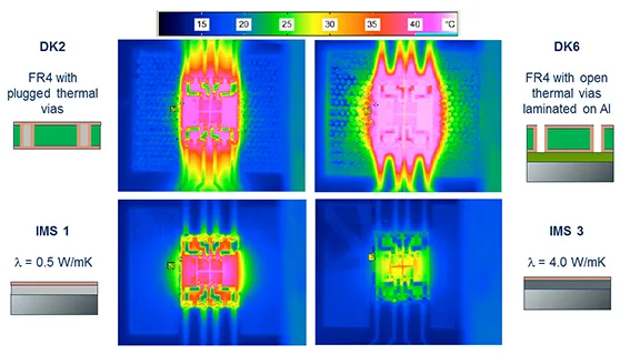
The most common PCB substrate is FR-4, a fiberglass-epoxy laminate with a thermal conductivity of about 0.25 W/m·K. While affordable, FR-4 isn’t ideal for high-heat applications. For better thermal performance, consider materials like polyimide (0.5 W/m·K) or metal-core substrates (1-2 W/m·K), which are often used in LED and power electronics.
2. Copper Weight and Thickness
Copper weight, measured in ounces per square foot (oz/ft2), affects both electrical and thermal conductivity. A standard 1 oz/ft2 copper layer is sufficient for low-power designs, but for high-current applications, opting for 2 oz/ft2 or higher can improve heat spreading. Thicker copper layers also reduce thermal resistance, helping to keep components cool.
3. Thermal Interface Materials (TIMs)
When attaching heatsinks or other cooling solutions, use high-quality TIMs like thermal grease or silicone pads. These materials fill microscopic gaps between surfaces, improving heat transfer with conductivities often in the range of 1-8 W/m·K.
Balancing Thermal Design with Standard PCB Dimensions
Designing for thermal efficiency often means working within the constraints of standard PCB dimensions thermal properties. A typical single-sided or double-sided board might measure 1.57 mm thick, but multi-layer boards for high-power applications can go up to 2.36 mm or more to accommodate additional copper planes for heat spreading.
When space is limited, prioritize thermal vias and copper pours over increasing board size. For compact designs, consider using metal-core PCBs, which offer superior heat dissipation without significantly altering dimensions. Balancing these factors ensures your board fits its intended application while maintaining thermal stability.
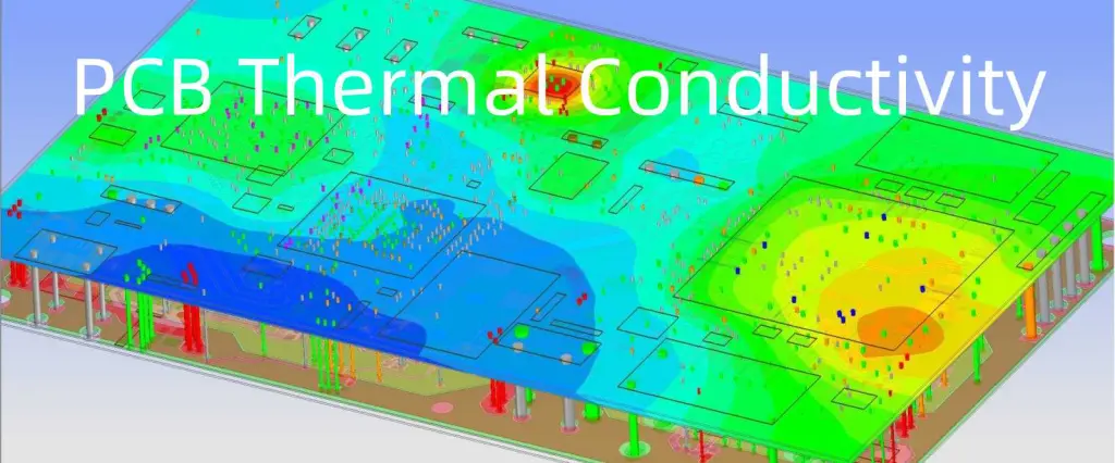
Tools and Simulations for Thermal Analysis
Before finalizing your design, use thermal simulation software to predict heat distribution and identify potential hotspots. Many design tools offer built-in thermal analysis features that model heat flow based on your layout and component specifications. Running a simulation can reveal whether a component’s junction temperature exceeds its maximum rating, often specified as 125°C for many ICs, allowing you to adjust your design accordingly.
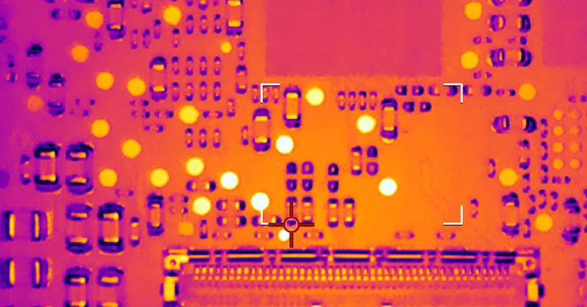
Thermal imaging cameras are also valuable during prototyping. They provide real-time data on heat distribution, helping you validate your design choices. Investing in these tools can save time and prevent costly redesigns down the line.
Conclusion: Designing for Heat and Space Efficiency
Thermal management is a cornerstone of reliable PCB design, especially when working within the constraints of standard dimensions. By focusing on PCB thermal design, employing effective PCB heat dissipation methods, adhering to component placement guidelines, making informed PCB material selection choices, and understanding standard PCB dimensions thermal properties, you can create boards that perform optimally without overheating.
Start with a well-thought-out layout, use copper planes and thermal vias to spread heat, and select materials that match your thermal needs. Whether you're designing for a small consumer device or a high-power industrial system, these strategies will help keep your components cool and extend the life of your PCB. With careful planning and the right tools, you can tackle thermal challenges head-on and ensure your designs stand the test of time.


