 ALLPCB


If you're looking to improve the reliability of your Surface Mount Technology (SMT) assembly process, you're in the right place. This guide dives deep into SMT component placement guidelines, solder paste stencil design, reflow soldering profile optimization, SMT assembly equipment, and troubleshooting SMT defects. Whether you're an engineer or a manufacturer, these best practices will help you achieve consistent, high-quality results in your PCB assembly projects.
In the sections below, we'll break down each aspect of SMT design and assembly with actionable tips, detailed explanations, and practical examples to ensure your process is as smooth and reliable as possible.
What is Surface Mount Technology (SMT) and Why Does It Matter?
Surface Mount Technology (SMT) is a method of assembling electronic components directly onto the surface of a printed circuit board (PCB). Unlike traditional through-hole technology, SMT allows for smaller components, higher density, and faster production, making it the go-to choice for modern electronics like smartphones, laptops, and IoT devices. Over 90% of electronic devices today rely on SMT for their compact and efficient designs.
However, the benefits of SMT come with challenges. Smaller components and tighter tolerances mean that even minor errors in design or assembly can lead to defects, rework, or product failures. Following best practices in SMT design is critical to ensuring reliability and reducing costs in the long run.

SMT Component Placement Guidelines for Precision and Reliability
Proper component placement is the foundation of a successful SMT assembly. Misaligned or poorly placed components can cause issues like tombstoning, solder bridges, or mechanical stress. Here are key guidelines to follow:
- Spacing and Clearance: Ensure adequate spacing between components to avoid interference during placement and soldering. For example, maintain a minimum clearance of 0.2 mm between small passive components (like 0402 or 0603 packages) to prevent solder bridging.
- Orientation: Align components with similar orientations whenever possible to simplify pick-and-place machine programming. For polarized components like diodes and capacitors, ensure correct polarity marking on the PCB layout matches the component.
- Thermal Considerations: Place heat-sensitive components away from high-power components or heat sinks. For instance, avoid placing small SMD capacitors near power transistors that generate significant heat during operation.
- Fiducial Markers: Include fiducial markers on the PCB for precise alignment during automated placement. A minimum of three markers, with a diameter of 1-2 mm, placed diagonally across the board, helps machines achieve placement accuracy within 0.05 mm.
By adhering to these guidelines, you can minimize placement errors and improve the overall reliability of your assembly process.
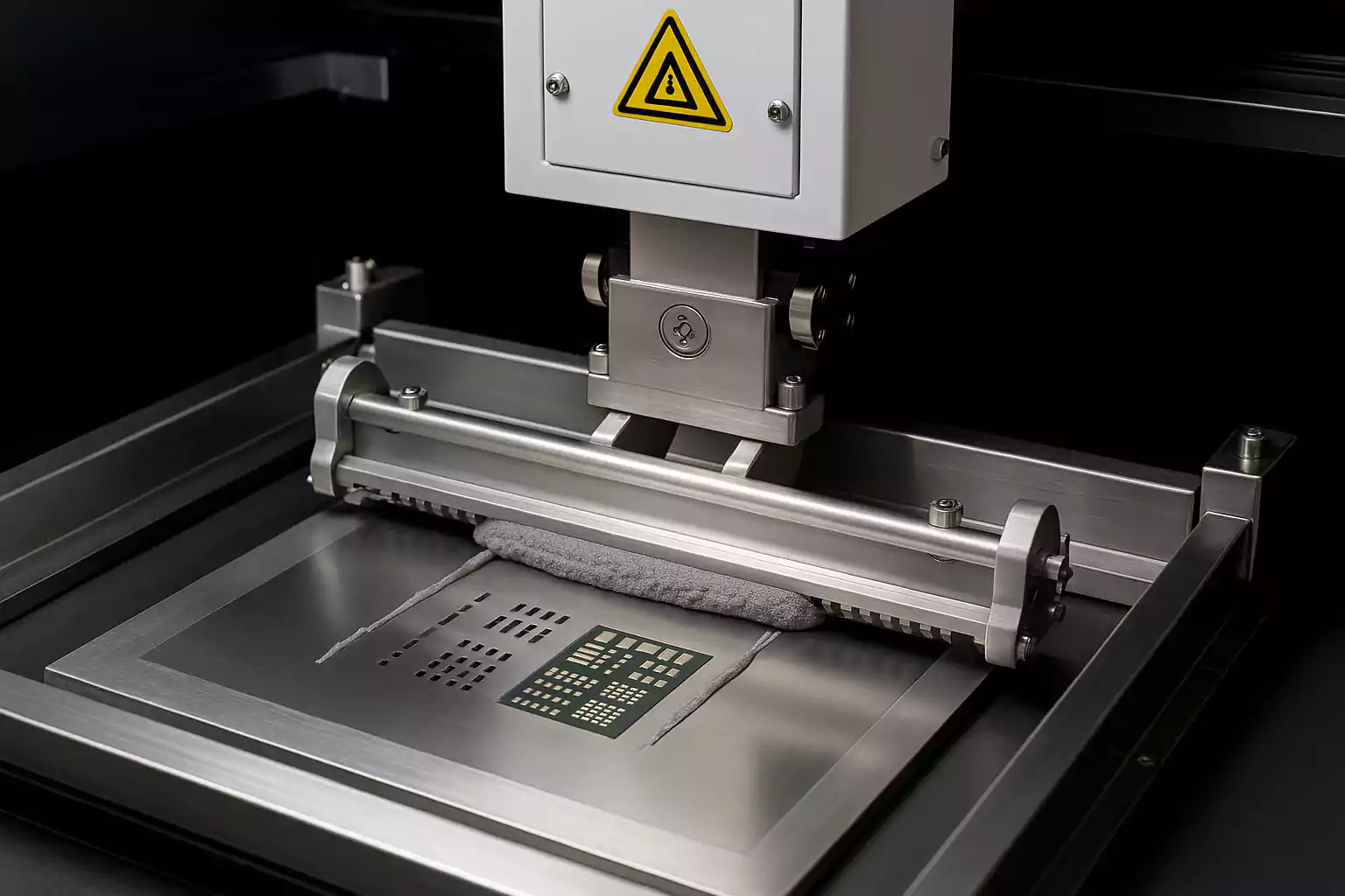
Solder Paste Stencil Design: Getting the Foundation Right
Solder paste stencil design is a critical step in SMT assembly, as it directly affects the quality of solder joints. Poor stencil design can lead to insufficient paste, smearing, or uneven deposition, causing defects like incomplete joints or bridging. Here are best practices for effective stencil design:
- Stencil Thickness: Choose the right stencil thickness based on component size. For fine-pitch components (e.g., 0.4 mm pitch QFNs), a thinner stencil of 0.1 mm works best to control paste volume. For larger components, a thickness of 0.15-0.2 mm may be more suitable.
- Aperture Design: Match aperture sizes to pad dimensions, typically reducing the aperture by 10-20% for better paste release. For ultra-small components like 0201 packages (0.6 x 0.3 mm), use rounded apertures to improve separation and reduce paste volume.
- Solder Mask Clearance: Maintain a solder mask clearance of at least 0.1 mm around pads to prevent paste from spreading onto unintended areas, which can cause bridging.
- Material and Finish: Use stainless steel stencils with a laser-cut finish for precision and durability, especially for high-volume production runs.
A well-designed stencil ensures consistent solder paste application, which is crucial for reliable soldering. Research shows that over 60% of SMT soldering defects originate during the printing process, so getting this step right is essential.
Reflow Soldering Profile Optimization for Strong Joints
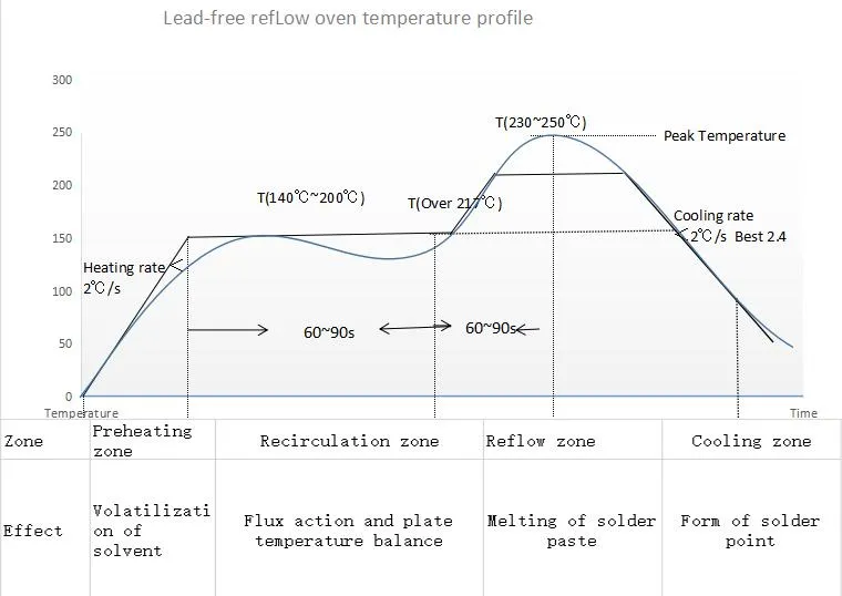
Reflow soldering is the process of melting solder paste to form strong, reliable joints between components and the PCB. Optimizing the reflow profile ensures proper solder flow without damaging components. Here's how to fine-tune your reflow soldering profile:
- Preheat Phase: Gradually heat the board to 150-180°C over 60-90 seconds to activate flux and evaporate solvents. This prevents thermal shock to components and reduces the risk of defects like tombstoning.
- Soak Phase: Maintain a temperature of 180-200°C for 60-120 seconds to ensure even heat distribution across the board. This step minimizes temperature gradients that could cause uneven soldering.
- Reflow Phase: Raise the temperature to a peak of 235-250°C (depending on solder alloy) for 20-40 seconds to melt the solder paste completely. For lead-free solder (e.g., SAC305), aim for a peak of 245°C to ensure proper wetting.
- Cooling Phase: Cool the board at a rate of 2-4°C per second to solidify solder joints without inducing thermal stress. Rapid cooling can lead to brittle joints, while slow cooling may cause excess intermetallic growth.
Regularly monitor and adjust the reflow profile using thermocouples attached to the PCB to account for variations in board size, component density, or oven performance. A well-optimized profile reduces defects like voiding, where air pockets in solder joints weaken connections.
SMT Assembly Equipment: Choosing the Right Tools
The quality of SMT assembly heavily depends on the equipment used. Investing in reliable tools and maintaining them properly can significantly boost production efficiency and reduce errors. Here are key considerations for SMT assembly equipment:
- Pick-and-Place Machines: Choose machines with vision systems for precise component placement, especially for fine-pitch and ultra-small components. High-speed machines can handle up to 100,000 components per hour, but accuracy matters more than speed for complex designs.
- Solder Paste Printers: Automated printers with optical alignment ensure consistent paste deposition. Look for models with adjustable squeegee pressure (typically 8-12 kg) to adapt to different stencil designs.
- Reflow Ovens: Select ovens with multiple heating zones (at least 5-7) for better control over the reflow profile. Convection ovens are preferred for uniform heating across densely populated boards.
- Inspection Systems: Automated Optical Inspection (AOI) systems can detect placement errors, missing components, and solder defects with over 95% accuracy, reducing the need for manual inspection.
Regular calibration and maintenance of equipment are just as important as choosing the right tools. For instance, calibrating pick-and-place nozzles ensures consistent handling of components, preventing misalignment.

Troubleshooting SMT Defects: Identifying and Fixing Common Issues
Even with the best practices in place, SMT assembly can encounter defects. Knowing how to identify and resolve these issues quickly saves time and resources. Below are common SMT defects and their solutions:
- Tombstoning: This occurs when one end of a component lifts off the pad during reflow, resembling a tombstone. It’s often caused by uneven heating or excessive solder paste. To fix it, optimize the reflow profile for balanced heating and reduce paste volume by adjusting stencil apertures.
- Solder Bridges: These are unintended connections between pads due to excess solder. Prevent bridges by ensuring a solder mask clearance of at least 0.1 mm and using a stencil with smaller apertures (10-20% reduction) for fine-pitch areas.
- Incomplete Solder Joints: Weak or missing joints result from insufficient solder paste or improper reflow temperatures. Check stencil alignment and increase peak reflow temperature if needed, ensuring it stays within component tolerances (e.g., 245°C for lead-free solder).
- Component Misalignment: Misaligned components often stem from pick-and-place errors. Use vision systems for precise placement and verify component orientation in the feeder setup before starting production.
- Voiding: Air pockets in solder joints weaken connections and are common in BGA packages. Minimize voiding by using a "window pane" pad design for large thermal pads, allowing flux fumes to escape during reflow, and ensuring proper preheat and soak phases.
Implementing a robust inspection process, such as AOI or X-ray for hidden joints, helps catch defects early. Keeping detailed records of defects and their causes also aids in refining your process over time.
Why Following SMT Best Practices Matters
Adhering to best practices in SMT design and assembly isn’t just about avoiding defects—it’s about ensuring long-term reliability and efficiency. Poorly assembled PCBs can lead to field failures, costly recalls, and damaged reputation. By focusing on precise component placement, optimized stencil design, tailored reflow profiles, reliable equipment, and proactive troubleshooting, you can achieve consistent quality and meet the demands of modern electronics.
At ALLPCB, we’re committed to supporting your SMT assembly needs with high-quality manufacturing services and expert guidance. Whether you’re working on a small prototype or a large production run, applying these best practices will help you build better products with fewer headaches.
Conclusion: Building Better with SMT Design
Surface Mount Technology offers incredible advantages for creating compact, high-performance electronics, but success depends on attention to detail. From following SMT component placement guidelines to mastering solder paste stencil design, optimizing reflow soldering profiles, selecting the right SMT assembly equipment, and effectively troubleshooting SMT defects, every step plays a vital role in reliable assembly.
Start implementing these best practices in your next project to improve quality, reduce defects, and streamline production. With the right approach, SMT can be a game-changer for your designs, delivering results that meet even the most stringent requirements.


