ALLPCB


Purpose of sum-and-difference beams
The purpose of forming sum and difference beams in a phased-array is to improve the array's angular measurement accuracy. Because the antenna beam has a finite 3 dB beamwidth, sum-and-difference beam techniques are often introduced to increase angle measurement precision. A 26 GHz phased-array radar typically provides three output channels: a sum channel, an azimuth-difference channel, and an elevation-difference channel. The sampling method is the half-array method: summing the directional patterns of the left and right elements (or the top and bottom elements for elevation) yields the sum beam, while subtracting them yields the difference beam. By taking the ratio of the signals from these two receive channels, higher angular accuracy can be obtained in azimuth. Similarly, the ratio between the elevation-difference channel and the sum channel can provide improved elevation angle accuracy. Because the principles are the same, the following discussion focuses on the azimuth direction.
Principle of sum-and-difference beams
In a phased-array radar, each transmit or receive channel can be phase compensated to achieve coherent signal addition at a target direction. Therefore, phased arrays include phase shifters (also described as weighting, which introduces a phase weight to each output).
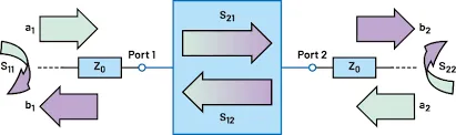
After weighting and summing the receive branches, the sum-beam channel is formed. To obtain the difference beam channel, the array is split into two front-end halves; each half is summed separately and then the two results are subtracted. This produces one sum channel and one difference channel. See Figure below:
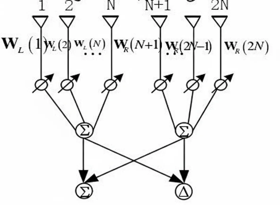
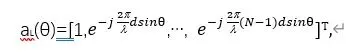
Assume a uniform linear array (in the azimuth direction) with element spacing d and a total of 2N elements, and a target at actual direction θ. Using Figure 2 as an example and taking the first element as the reference, the steering vector of the left subarray is shown in Figure 3:
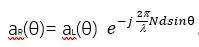
The steering vector of the right subarray is shown in Figure 4:
Let W denote the array weighting. To steer the beam to θ0, choose WL = aL(θ0) and WR = aR(θ0). Assuming ideal amplitude (all element amplitudes equal to 1), the output of the left subarray is:
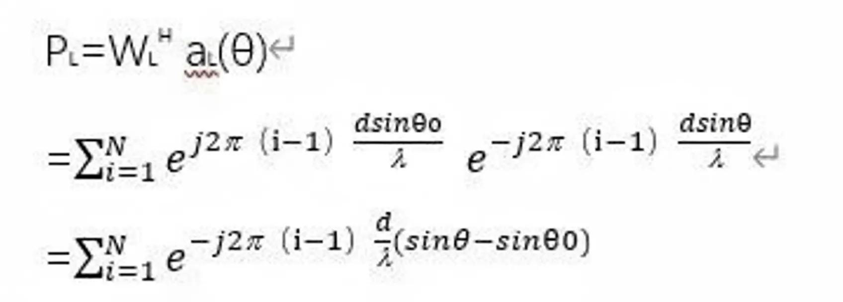
The phase of the left-subarray signal is determined by the phase-shifter settings and the phase term aL(θ) introduced by element spacing, as shown in Figure 6:

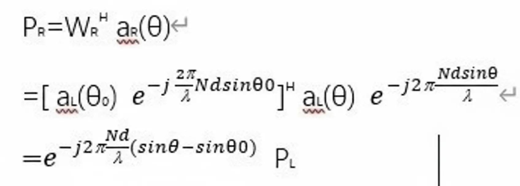
Similarly, the output of the right subarray is:
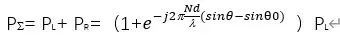
The sum beam is:
The difference beam is:
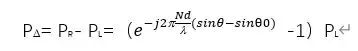
The ratio of the two is:
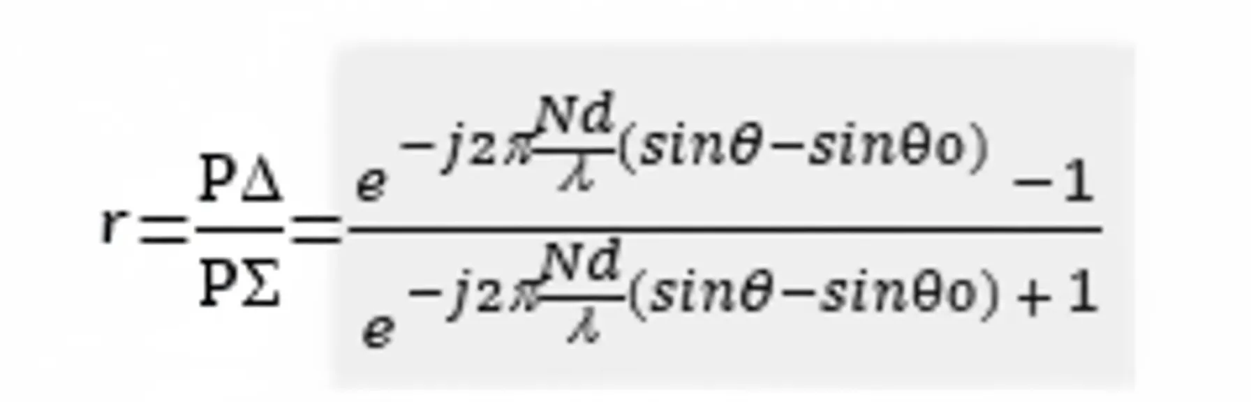
From the expression above, the ratio of the difference beam to the sum beam provides the angular difference between the beam steering direction and the actual target direction, which enables improved angle measurement accuracy. The same approach applies to elevation, with the left and right subarrays analogous to top and bottom subarrays for elevation processing.