 ALLPCB


If you're designing video printed circuit boards (PCBs) and struggling with noise or signal issues, grounding is likely the key to solving your problems. Proper grounding techniques can drastically reduce noise and improve signal integrity in video PCBs. In this comprehensive guide, we'll explore the best grounding practices for video PCBs, diving deep into strategies that ensure optimal performance for high-speed video signals. Whether you're a seasoned engineer or just starting out, this post will provide actionable tips to enhance your designs.
Why Grounding Matters for Video PCBs
Video PCBs handle high-frequency signals, often in the range of several hundred megahertz to gigahertz, to transmit crisp, clear video data. At these speeds, even small issues with grounding can lead to significant noise interference or signal degradation. Poor grounding can cause problems like crosstalk, electromagnetic interference (EMI), and jitter, which directly impact video quality with artifacts or flickering on the screen.
Grounding serves as the foundation for a stable electrical environment. It provides a low-impedance path for return currents, shields sensitive signals from interference, and minimizes voltage differences across the board. For video applications, where signal integrity is critical, optimizing grounding isn't just a good practice—it's essential.
Key Challenges in Video PCB Grounding
Before diving into solutions, let's look at the common grounding challenges specific to video PCBs:
- High-Frequency Noise: Video signals operate at high frequencies, making them prone to noise coupling from nearby traces or external sources.
- Signal Integrity Issues: Impedance mismatches or improper return paths can distort video signals, leading to data errors.
- EMI Sensitivity: Without proper shielding, video PCBs can emit or pick up EMI, degrading performance.
- Ground Loops: Multiple ground connections can create loops, introducing unwanted currents and noise.
Understanding these challenges helps in crafting effective grounding strategies tailored for video applications. Let's explore the best practices to address them.
Best Grounding Practices for Video PCBs
Here, we'll break down proven techniques to optimize grounding for video PCBs. These strategies focus on reducing noise and improving signal integrity, ensuring your video signals remain clear and reliable.
1. Use a Dedicated Ground Plane
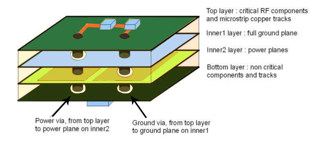
A solid ground plane is the backbone of effective grounding in video PCBs. This is a large, continuous copper layer dedicated solely to grounding, providing a low-impedance path for return currents. For video designs, a ground plane helps minimize noise by keeping return paths short and direct.
In a typical 4-layer PCB stack-up for video applications, place the ground plane directly below the signal layer carrying high-speed video traces. This setup reduces loop inductance, which can be as low as a few nanohenries, compared to longer return paths that might reach tens of nanohenries and cause noise spikes.
Tip: Avoid splitting the ground plane unless absolutely necessary for mixed-signal designs. A split plane can disrupt return paths, especially for high-frequency video signals above 500 MHz, leading to signal distortion.
2. Implement Short and Direct Return Paths
High-speed video signals require the shortest possible return paths to minimize inductance and maintain signal integrity. When a signal travels along a trace, its return current flows through the ground plane beneath it. If the return path is interrupted or too long, it can create noise and delay, affecting video output.
To ensure short return paths, route critical video signals, such as HDMI or DisplayPort traces, directly above a continuous ground plane. Avoid routing over splits or gaps in the ground layer, as this forces return currents to take longer detours, increasing inductance by up to 20-30% in some cases.
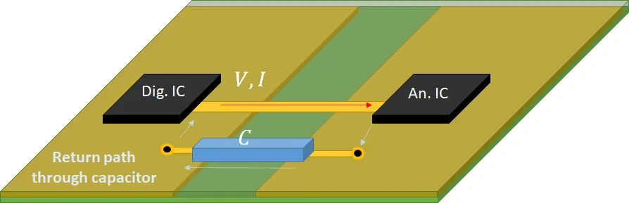
3. Separate Analog and Digital Grounds for Mixed-Signal Designs
Many video PCBs combine analog and digital components, such as analog video amplifiers and digital signal processors. Mixing these grounds can introduce noise from digital switching into sensitive analog circuits, degrading video quality.
A common practice is to use separate ground planes for analog and digital sections, connecting them at a single point near the power supply entry. This technique, often called a "star grounding" approach, prevents digital noise, which can peak at levels of 100 mV or more during switching, from coupling into analog signals with thresholds as low as 10 mV.
4. Utilize Stitching Vias for Ground Plane Integrity
In multilayer video PCBs, stitching vias are small conductive holes that connect ground planes across different layers. These vias maintain ground continuity, especially in areas where signal traces or components interrupt the plane. They also help reduce EMI by creating a Faraday cage-like effect around high-speed signals.
Place stitching vias around the edges of the PCB and near high-frequency video signal traces. Space them at intervals of about 1/10th of the wavelength of the highest frequency signal— for a 1 GHz video signal, this translates to spacing vias roughly every 30 mm. This practice can reduce EMI radiation by up to 10 dB in critical frequency bands.
5. Minimize Ground Loops with Proper Layout
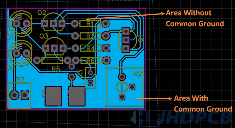
Ground loops occur when multiple ground paths create a loop, allowing unwanted currents to flow and introduce noise. In video PCBs, this can manifest as flickering or distortion in the output. To avoid ground loops, ensure all components connect to the ground plane through a single, common point wherever possible.
For example, when designing a video capture card, route all ground connections for connectors, ICs, and decoupling capacitors to the same ground plane without creating alternate paths. This reduces the risk of differential voltages, which can be as small as 5 mV but still disrupt video signals with tight noise margins.
Advanced Video PCB Grounding Techniques for Noise Reduction
Beyond the basics, advanced grounding strategies can further enhance performance in demanding video applications. These methods tackle specific noise sources and signal integrity challenges.
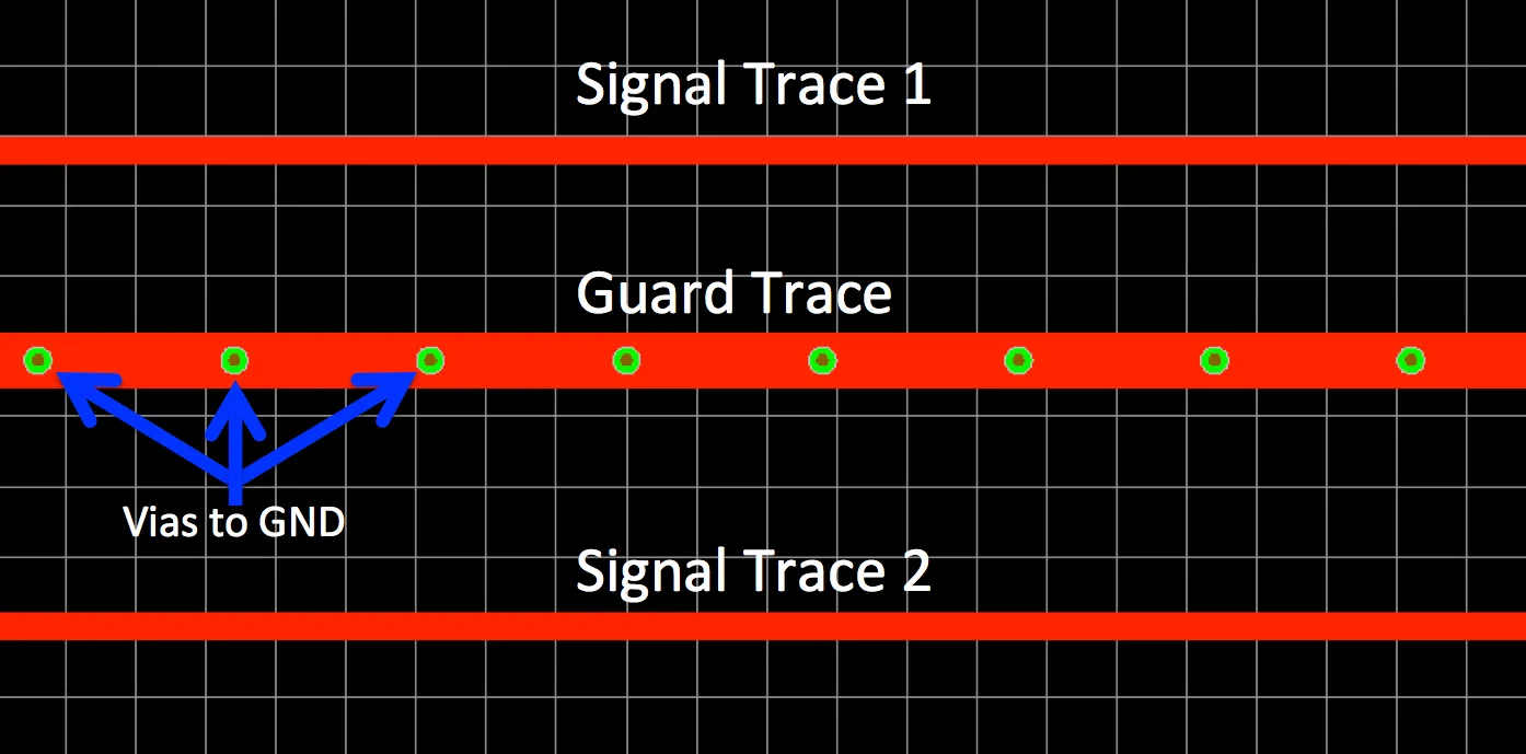
6. Use Guard Traces for High-Speed Video Signals
Guard traces are grounded traces placed alongside sensitive video signal lines to shield them from crosstalk. For differential pairs like those in HDMI or USB-C video interfaces, place guard traces on either side, connected to the ground plane with vias at regular intervals (every 10-15 mm for signals above 1 GHz).
This technique can reduce crosstalk by up to 15-20%, ensuring cleaner video transmission, especially in densely packed PCB layouts where trace spacing might be as tight as 0.1 mm.
7. Optimize Decoupling Capacitors Placement
Decoupling capacitors stabilize power delivery and filter noise, but their effectiveness depends on proper grounding. Place these capacitors as close as possible to the power pins of video processing ICs, with their ground pads directly connected to the ground plane via short traces or vias.
For high-speed video chips, use a combination of capacitor values, such as 0.1 μF and 1 μF, to cover a wide frequency range of noise suppression. Ensure the loop area between the capacitor, IC pin, and ground is minimized to keep inductance below 1 nH, preventing noise spikes during fast signal transitions.
8. Control Impedance with Ground Planes
Signal integrity in video PCBs heavily depends on controlled impedance, especially for traces carrying signals at speeds of 5 Gbps or higher. A ground plane beneath the signal layer helps maintain consistent impedance, typically targeting values like 50 ohms for single-ended traces or 100 ohms for differential pairs.
Use PCB design software to calculate trace width and spacing based on the dielectric constant of your board material (often around 4.5 for standard FR-4). A continuous ground plane ensures the return current follows the signal path closely, reducing reflections that can degrade video quality.
Common Mistakes to Avoid in Video PCB Grounding
Even with the best intentions, certain grounding mistakes can undermine your video PCB design. Here are pitfalls to watch out for:
- Splitting Ground Planes Unnecessarily: Cutting the ground plane for non-critical reasons disrupts return paths and increases noise.
- Ignoring Via Placement: Failing to use enough stitching vias can create ground discontinuities, especially in multilayer boards.
- Overlooking Component Placement: Placing noisy components near sensitive video traces without proper grounding can introduce interference.
By steering clear of these errors, you can maintain the integrity of your grounding strategy and achieve better performance in video applications.
Tools and Resources for Effective Grounding
Designing optimal grounding for video PCBs is easier with the right tools. PCB design software with simulation capabilities can model ground planes, return paths, and EMI effects before fabrication. Look for features that allow you to analyze impedance and signal integrity for high-speed video signals.
Additionally, reference design guides for video interfaces like HDMI, DisplayPort, or MIPI can provide specific grounding recommendations tailored to those standards. These resources often include layout examples and stack-up suggestions to minimize noise.
Conclusion: Building Better Video PCBs with Grounding
Grounding is a critical factor in designing video PCBs that deliver clear, reliable signals. By using dedicated ground planes, ensuring short return paths, separating analog and digital grounds, and applying advanced techniques like guard traces and stitching vias, you can significantly reduce noise and improve signal integrity. These best grounding practices for video PCBs tackle the unique challenges of high-frequency signals, ensuring your designs perform at their best.
Whether you're working on a consumer video device or a professional-grade system, take the time to plan your grounding strategy carefully. A well-grounded PCB not only enhances video quality but also reduces debugging headaches down the line. With these video PCB grounding techniques in your toolkit, you're well-equipped to create high-performing, noise-free designs.


