Introduction
In power module applications, EMC design is often critical because it affects the overall electromagnetic compatibility performance of the product. This article examines how to improve EMC performance from the perspective of power module design and application.
EMC Basics
EMC testing describes two aspects of product performance: electromagnetic emissions (EME) and electromagnetic immunity (EMS). EME includes conducted and radiated emissions, while EMS covers phenomena such as electrostatic discharge, electrical fast transients, and surge. To improve system stability, the following sections describe common methods to optimize power module EMC, covering surge protection, PCB and circuit design, and conducted-noise mitigation.
Surge Protection Circuits
Engineers commonly use surge protection circuits to ensure EMC performance and system stability. Surge voltages can originate from lightning, short-circuit faults, frequent power cycling, and other causes. To increase the input-stage surge protection capability, varistors (MOVs) and TVS diodes are often added externally.
When attempting two-stage protection, incorrect arrangements can be counterproductive. If MOV2 has a lower clamping voltage or lower surge current rating than MOV1, MOV2 may fail prematurely under strong surge conditions, causing system failure. Similarly, if a TVS is used together with an MOV and the TVS responds faster than the MOV, the TVS may conduct and be damaged before the MOV takes effect. A correct approach is to separate the protection devices into two stages by adding an inductance between the two MOVs or between an MOV and a TVS, as this provides staged energy absorption and improves overall robustness.
Two-Stage Surge Protection Details
Alternatively, a resistor can be placed between an MOV and a TVS to prevent the TVS from conducting first and failing. When selecting the resistor, consider its power dissipation so the resistor does not fail before the protection devices. A parallel capacitor can also be used to absorb energy and increase surge-withstand capability.
PCB Design for Power Modules
Power module products have specific PCB design requirements that include thermal design, EMC, interference control, and manufacturability. PCB design is one of the most important stages in power module product development and must address heat dissipation, EMC routing, and assembly constraints.
Internal Circuit Design of Power Modules
Power modules are typically switching power supplies rather than linear types. During switching transitions, both voltage and current are chopped, producing large transient changes (di/dt, dv/dt), which make switching supplies significant sources of EMC interference. Common isolated topologies include forward and flyback. Through careful internal circuit design combined with PCB layout, the module's EMC performance can be optimized.
Conducted Noise Design
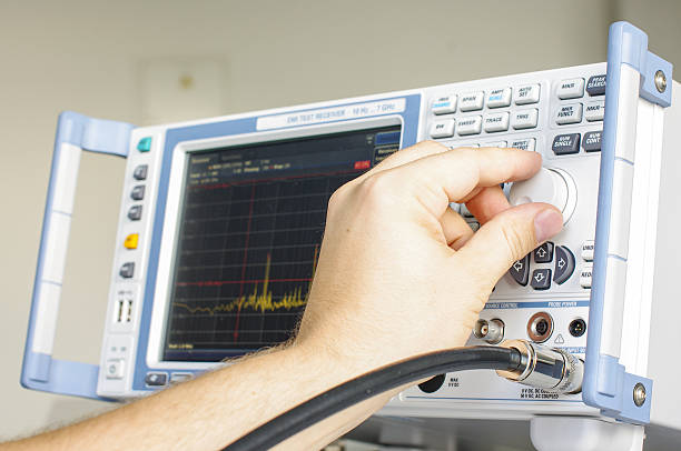
Designing the conducted-noise suppression for a power module begins with analyzing the module's conducted-noise profile and then applying appropriate countermeasures. Using an oscilloscope, typical frequency regions and suggested solutions are:
- Low frequency: 150 kHz to 1 MHz, particularly at the switching frequency point — differential-mode noise. Solution: differential-mode filter.
- Mid frequency: 1 MHz to 10 MHz — both differential-mode and common-mode noise. Solution: add appropriate common-mode filtering in addition to differential filtering.
- High frequency: 10 MHz to 30 MHz — common-mode noise. Solution: common-mode filter.
Therefore, to address conducted-noise issues, add both differential-mode and common-mode filters along the module's transmission path.
Experience note: If an oscilloscope measurement shows a module's frequency range from 30 MHz to 1000 MHz and the conducted-noise amplitude rises linearly at high frequency without any downward trend, the product's radiated emissions are generally likely to be poor.
Summary
EMC testing is highly practical, but understanding basic principles helps guide pretest circuit design and shortens project development time. A well-designed surge protection circuit combined with careful module circuit and PCB design improves the stability and reliability of the system power supply.
 ALLPCB


