ALLPCB


Overview
This article discusses battery management systems and their unique requirements for always-on wearable devices. It examines battery management ICs from Maxim Integrated that simplify charging and maintenance for wearables, then reviews two Adafruit lithium-ion batteries.
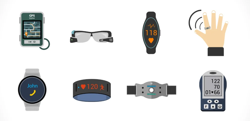
Using Rechargeable Batteries in Consumer Devices
Wearables are consumer products, so they are influenced by consumer expectations for satisfaction. Users expect long intervals between charges and expect batteries to last many years before replacement. The latter is especially important because wearables are often not user-serviceable: there is no removable battery cover and small rear screws are not intended for customer removal.
During operation, batteries and wearables must withstand the range of temperatures and conditions typically encountered during daily use. The chosen battery chemistry must also provide high energy density to deliver significant power in a small package.
Although many battery chemistries are available, lithium-ion batteries have become the standard for most consumer rechargeable devices. Lithium-ion batteries offer very high energy density; compared with the nearest competitor, nickel-cadmium (NiCd) cells, the watt-hour capacity in the same package is roughly twice as high. The industry standard nominal cell voltage for lithium-ion is 3.6 V ± 0.1 V, which allows a wearable to be powered by a single cell.
Engineers should avoid designing wearables that require active user maintenance of the battery chemistry. This excludes nickel-cadmium cells, which require periodic charge-discharge cycles due to memory effects. Lithium-ion batteries do not have this memory effect and do not require periodic cycling to maintain capacity.
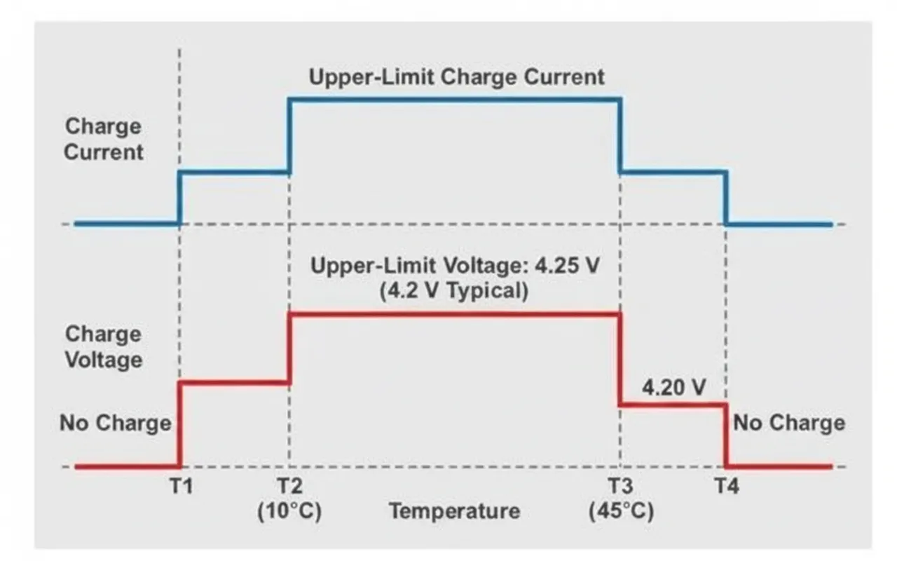
Unlike NiCd cells, lithium-ion batteries require electronic management within the system. They must be charged using a controlled constant-current, constant-voltage regime or a combination of both. During charging, protection circuitry is required to prevent voltage or current spikes that could damage the cell or render it unusable. Lithium-ion cells can also be damaged by extreme high or low temperatures, so temperature monitoring is necessary. Very low temperatures can render a cell unusable, while very high temperatures can be hazardous and may lead to thermal runaway, where heat generation accelerates and causes further heat release.
Even when unused, lithium-ion cells age and lose capacity over time. As a cell ages, it requires more frequent charging. Cell manufacturers typically do not specify an exact capacity loss profile. While an aged battery pack made of multiple 3.6 V cells may be less noticeable, aging of a single 3.6 V cell can be a significant design concern. A fuel gauge should track capacity loss over time to compensate for such differences.
Unique Battery Requirements for Always-On Wearables
For battery-powered consumer devices, users expect a reliable and consistent battery fuel gauge. Consumers understand that a multifunction mobile device will deplete faster while playing video than when idle. However, for always-on wearables, users expect the battery gauge reading, presented as a percentage or bars, to decline at a consistent and predictable rate. Users who check a wrist-worn wearable daily will notice inconsistencies. For example, if a device normally loses 10% per day but one day shows a 25% drop, users will notice and may complain. Therefore, the device battery management circuit must accurately monitor and maintain battery health to provide reliable gauge readings.
The most obvious limitation in wearables is size. Most current wearables use a single 3.6 V lithium-ion cell. Even well-maintained and healthy lithium-ion cells heat up and swell under load. Designers must allocate space inside the enclosure for potential cell swelling to avoid safety issues.
At the low voltages typical for single-cell wearables, catastrophic current spikes are less likely, but concurrent activation of multiple sensors and adverse event combinations can create large current transients that may damage the cell. Fortunately, protection for the modest voltages and currents involved is relatively straightforward.
Battery Management for Wearables
Lithium-ion cells require continuous monitoring of terminal voltage, current draw, and temperature. Monitoring functions must remain stable and reliable over time, which can consume development resources if implemented from scratch.
Specialized ICs designed for battery management can greatly simplify monitoring. Maxim Integrated's MAX17301X+ is a single-cell fuel gauge with battery protection, providing a complete battery management system for a single 3.6 V lithium-ion cell (see Figure 1).
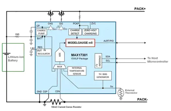
Figure 1: The MAX17301X+ from Maxim Integrated is a complete lithium-ion battery management system that monitors and protects a single 3.6 V cell and supports safe charging. It communicates with most microcontrollers over a standard I2C interface.
The MAX17301X+ is offered in a 15-pin WFBGA package measuring 1.68 x 2.45 mm, making it suitable for wearables. Its active current is only 24 microamps, which is appropriate for low-power devices.
The MAX17301X+ integrates many complex functions for managing a 3.6 V lithium-ion cell. Charge and discharge FETs are used to supply power to the battery and the wearable system. When a cell is connected, the MAX17301X+ continuously monitors terminal voltage, the current through an external sense resistor, and the temperature of both the IC and the cell.
To address temperature-related issues, two temperature sensors can be used: an internal sensor and an external battery sensor. The external sensor connects to the TH pin and can be placed inside or adjacent to the cell. If the external sensor is omitted, the MAX17301X+ should be positioned on the side of the cell so the internal sensor reflects cell temperature. Charge and discharge FETs should also be placed close to the MAX17301X+ so their heat is included in temperature analysis.
The MAX17301X+ communicates with the host microcontroller over a standard I2C interface. The IC includes programmable registers that allow alarm limits and conditions to be set according to battery manufacturer specifications. These initial values can be programmed by the host or set during factory testing. Most values are stored in nonvolatile memory (NVM) registers, so they are retained if the cell is removed. Checksums are used to verify NVM integrity.
Discharge Protection
During discharge, the MAX17301X+ provides three forms of protection: overcurrent, overtemperature, and undervoltage.
Excessive current draw reduces usable capacity, can damage a cell beyond recovery, and may cause fire. Overcurrent discharge protection can rapidly disable the wearable power supply within 70 microseconds, which is critical in short-circuit conditions. For small current transients, the response can be as slow as 23 seconds.
High temperature can have effects similar to overcurrent. If either the on-chip or external temperature sensor reaches a programmed threshold, overtemperature discharge protection will disable the wearable. In this condition, the MAX17301X+ will prevent the device from being powered until temperatures return to safe levels. The MAX17301X+ also includes a permanent fault thermal protection setting. If severe overheating is detected, the event is recorded and the charge and discharge FETs are permanently disabled, preventing device operation. This serves as a last line of defense against thermal runaway.
Cell voltages below the manufacturer-specified minimum can also damage a cell. Undervoltage discharge protection offers three levels of protection:
- Undervoltage protection can disable the discharge FET to cut power to the wearable device.
- Undervoltage shutdown is a lower-voltage setting that turns off the discharge FET and powers down the MAX17301X+ to save nanowatts.
- If the MAX17301X+ detects an open-circuit condition in the wearable electronics, SmartEmpty will disable the discharge FET to conserve power.
Charge Protection
During charging, protections similar to those for discharge are provided. The MAX17301X+ includes extensive programmable battery protection registers that allow tight control over nearly every aspect of battery maintenance (see Figure 2). Charge voltage and current settings are programmed per the battery manufacturer specifications.
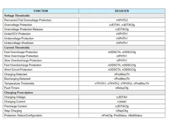
Figure 2: The MAX17301X+ provides extensive programmability, allowing designers to tune protection parameters to preserve battery life and safety.
The MAX17301X+ allows specifying charge voltage and current for six different temperature ranges to enable safe charging. Overcharge protection thresholds are also programmable. Because these charge parameters are battery-specific, wearable manufacturers generally discourage battery replacement, since replacement cells may not match factory specifications, potentially reducing life or creating unsafe conditions.
Overcharge current and voltage limits can be set for different temperature ranges. If a limit is exceeded, the MAX17301X+ will attempt to reduce voltage and current, disable the charge FET to stop charging, or permanently disable the charge FET in extreme fault conditions. Charge-temperature protections similarly disable charging at very low temperatures to avoid irreversible cell damage.
Battery State and Health
The MAX17301X+ also maintains a fuel gauge for the wearable. Coulomb counting is the most common method for estimating battery state. It records current flow history during charge and discharge to compute the net coulombs in and out of the cell. The MAX17301X+ measures current in both directions using the external sense resistor. Coulomb counting and associated algorithms are used to calculate the state of charge (SOC) as a percentage, which a wearable displays as the charge level.
Maxim Integrated uses a proprietary method similar to coulomb counting, called the ModelGauge m5 algorithm, to accurately compute SOC. The host microcontroller can read SOC values over I2C for display.
Another useful metric is the state of health (SOH), which is the ratio of the cell's available full capacity to the specified full capacity of a new cell. SOH declines as the cell ages and can be used to track aging effects described earlier.
Wearable Batteries
Battery selection for wearables is immediately constrained by size. Wearable batteries are typically single lithium-ion cells, sometimes including a basic protection circuit. Although datasheets provide recommended specifications, engineers should perform charge and discharge testing under different conditions to accurately assess cell behavior in the final product.
Adafruit's 4237 lithium-ion polymer cell is rated at 3.7 V and 350 mAh. With a cable attached, the cell measures 55 x 25 mm; without the cable, it measures 31 x 25 mm, slightly larger than a US quarter.
The 4237 cell specifies charging with constant current and voltage, recommending a charge current between 100 and 350 mA and a charge voltage of 3.7 V. Although specified at 3.7 V, a fully charged cell may show up to 4.2 V depending on temperature and current. It is important to set the battery management IC to match the cell specifications.
The 4237 includes a simple internal voltage protection circuit that temporarily disables output if the cell voltage falls below 3.0 V. The protection circuit also prevents overcharging.
Like many small lithium-ion cells, the 4237 lacks an internal temperature sensor or temperature protection. Using a dedicated battery management IC such as the MAX17301X+ is strongly recommended to protect the cell from temperature or current faults.
To increase capacity, Adafruit offers the 4236 3.7 V lithium-ion cell rated at 420 mAh. Its dimensions are 35 x 47 mm without the cable, making it slightly larger than the 4237 but with about 20% more capacity. Charging specifications are the same as the 4237, except the charge current can be up to 420 mA. It includes the same basic protection circuitry and also benefits from an external battery management IC.
Conclusion
Managing lithium-ion batteries for always-on wearables can be complex because many cells include limited or no built-in protection. Implementing proper protection and charge-discharge management adds cost and design time. However, programmable battery management ICs can greatly simplify the task while maintaining safety for the battery, the system, and the user, so designers do not need to implement protection from scratch.