ALLPCB


If you're facing issues with a printed circuit board (PCB) and wondering how to pinpoint and fix the problem, you're in the right place. This comprehensive PCB troubleshooting guide will walk you through the process of diagnosing and repairing faults like a pro. Whether you're dealing with shorts, open circuits, or mysterious malfunctions, we'll cover how to use a multimeter for PCB repair, leverage oscilloscope PCB diagnostics, and apply effective PCB fault isolation techniques. Let's dive into the step-by-step process to get your board back in working order.
Why PCB Troubleshooting Matters
PCBs are the backbone of modern electronics, from smartphones to industrial machinery. When a PCB fails, it can halt production, delay projects, or cause costly downtime. Knowing how to troubleshoot a PCB not only saves time and money but also builds your skills as an engineer or technician. Faults like shorts, open circuits, or component failures can be tricky to identify without the right approach and tools. This guide will equip you with the knowledge to tackle these challenges head-on using proven methods and diagnostic tools.
Essential Tools for PCB Troubleshooting
Before diving into the troubleshooting process, gather the necessary tools to diagnose and repair your PCB effectively. Here’s a list of must-have equipment:
- Multimeter: For measuring voltage, current, and resistance to identify shorts and open circuits.
- Oscilloscope: For analyzing signal behavior and detecting issues in dynamic circuits.
- Soldering Iron and Desoldering Tools: For replacing faulty components or fixing broken traces.
- Magnifying Glass or Microscope: For inspecting tiny components and solder joints.
- Schematic Diagrams: To understand the PCB layout and trace connections.
- Thermal Camera (Optional): For detecting overheating components due to shorts or failures.
Having these tools ready will make the troubleshooting process smoother and more efficient. Now, let’s break down the step-by-step guide to diagnosing and repairing PCBs.
Step 1: Visual Inspection – The First Line of Defense
Start with a thorough visual inspection of the PCB. Many issues, such as burnt components, cracked traces, or poor solder joints, can be spotted with the naked eye or a magnifying glass. Look for:
- Discolored or charred components indicating overheating.
- Broken or lifted traces on the board surface.
- Loose or cold solder joints that might cause intermittent connections.
- Physical damage like cracks or corrosion.
A visual check can often reveal obvious problems without the need for advanced tools. If you spot a damaged component, note its location and prepare to test it in the next steps.
Step 2: Power-Off Testing with a Multimeter for PCB Repair
Once you’ve completed the visual inspection, it’s time to use a multimeter for PCB repair. A multimeter is a versatile tool that helps identify issues like shorts and open circuits. Follow these steps with the power off to avoid damage:
Testing for Continuity
Set your multimeter to continuity mode (often indicated by a speaker symbol). Use the probes to check connections between points on the PCB based on the schematic diagram. If there’s no beep or reading when there should be a connection, you’ve likely found an open circuit. Typical resistance for a good trace should be close to 0 ohms.
Finding Shorts on PCBs
Short circuits occur when two unintended points on the board are connected, often causing malfunctions or overheating. To find shorts on PCBs, set the multimeter to continuity mode and test between adjacent traces or pins. If you hear a beep or see a low resistance reading (e.g., below 1 ohm) where there shouldn’t be a connection, you’ve identified a short. Common causes include solder bridges or damaged insulation.
Diagnosing Open Circuits on PCBs
An open circuit means there’s a break in the connection where current can’t flow. When diagnosing open circuits on PCBs, test along traces or between components and their pads. If the multimeter shows infinite resistance or no continuity, the trace or solder joint may be broken. Inspect the area closely for hairline cracks or lifted pads.
Step 3: Power-On Testing and Voltage Measurements
After power-off testing, power on the PCB (if safe) and use the multimeter to measure voltages at key points. Compare these readings to the expected values from the schematic or datasheet. For instance, if a microcontroller pin should output 3.3V but reads 0V, there could be a fault in the power supply or the component itself.
Be cautious when working with live circuits. Use insulated probes and avoid touching exposed metal parts to prevent shocks or shorting other components.
Step 4: Oscilloscope PCB Diagnostics for Signal Analysis
For more complex issues, especially in dynamic or high-frequency circuits, oscilloscope PCB diagnostics are invaluable. An oscilloscope lets you visualize electrical signals over time, helping you identify problems like noise, timing issues, or missing waveforms.
Setting Up the Oscilloscope
Connect the oscilloscope probe to the test point on the PCB, and attach the ground clip to a ground point on the board. Adjust the time base and voltage scale to match the expected signal. For example, if you’re testing a 1 MHz clock signal, set the time base to 1 μs/div to see the waveform clearly.
Analyzing Signals
Look for abnormalities in the signal. A square wave that appears distorted might indicate a capacitor failure, while a missing signal could point to a broken trace or dead component. Compare the observed waveform to the expected one from the design specs. If a signal is supposed to toggle between 0V and 5V but only reaches 3V, there might be a pull-down resistor issue or a failing driver.
Step 5: PCB Fault Isolation Techniques
PCB fault isolation techniques help narrow down the source of a problem systematically. Instead of testing every component, use these methods to focus your efforts:
Divide and Conquer
Split the circuit into sections based on the schematic. Test each section individually to isolate the faulty area. For example, if a power supply circuit isn’t working, check the input voltage first, then the regulator output, and finally the load connections.
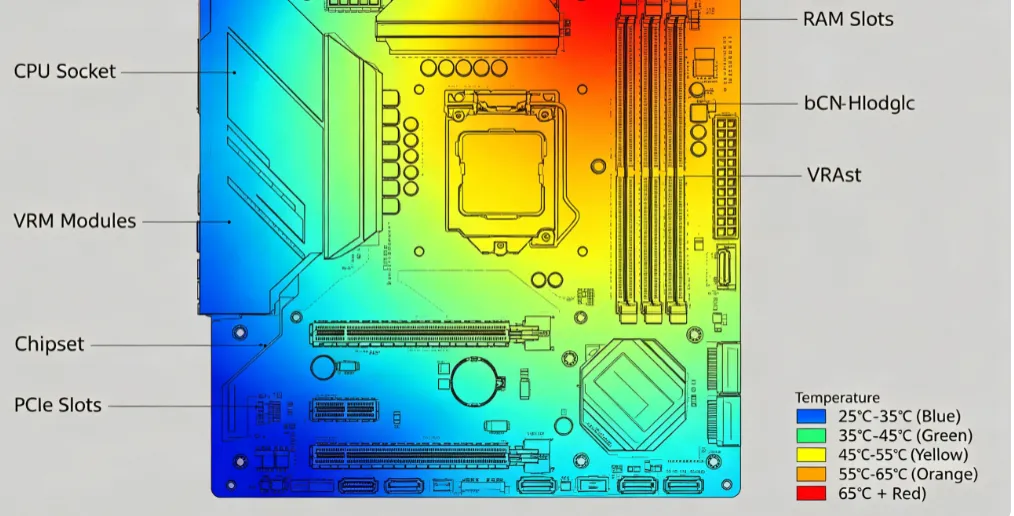
Thermal Imaging (Optional)
If available, a thermal camera can quickly spot overheating components caused by shorts or excessive current draw. A component running at 80°C (176°F) while others are at 40°C (104°F) is a red flag for a potential issue.
Signal Injection
For complex boards, inject a known signal at one point and trace it through the circuit using an oscilloscope. If the signal disappears or distorts at a specific stage, you’ve isolated the fault to that area.
Step 6: Repairing the Fault
Once you’ve identified the issue, it’s time to fix it. Depending on the problem, repairs might include:
- Replacing Components: Use a soldering iron to desolder and replace faulty components like resistors, capacitors, or ICs. Ensure the replacement matches the original specs (e.g., a 10kΩ resistor with 1% tolerance).
- Fixing Traces: For broken traces, carefully scrape off the solder mask and bridge the gap with a small wire or conductive paint.
- Removing Shorts: If a solder bridge causes a short, use desoldering wick or a suction tool to remove excess solder.
After making repairs, retest the board with a multimeter and oscilloscope to confirm the issue is resolved.
Step 7: Prevent Future Failures
Troubleshooting is only part of the process. To avoid recurring issues, take preventive measures:
- Double-check soldering quality during assembly to prevent cold joints.
- Use proper ESD (electrostatic discharge) protection to avoid damaging sensitive components.
- Ensure the PCB design accounts for thermal management to prevent overheating.
- Store and handle boards in a clean, dry environment to avoid corrosion.
Common PCB Issues and Quick Fixes
Here’s a quick reference for common PCB problems and their solutions:
- Short Circuits: Check for solder bridges or damaged traces. Use a multimeter to locate and remove the short.
- Open Circuits: Inspect for broken traces or lifted pads. Repair with a wire or conductive material.
- Component Failure: Test components with a multimeter and replace if readings are out of spec (e.g., a capacitor with 0 μF capacitance).
- Signal Issues: Use an oscilloscope to analyze waveforms and identify noise or timing problems.
Tips for Efficient PCB Troubleshooting
To streamline your troubleshooting process, keep these tips in mind:
- Always start with a visual inspection before moving to electrical testing.
- Work systematically by following the schematic and testing one section at a time.
- Document your findings, such as voltage readings or resistance values, to track patterns or recurring issues.
- Keep a clean workspace to avoid introducing new faults like static discharge or debris.
Conclusion: Mastering PCB Troubleshooting
Troubleshooting PCBs like a pro requires a blend of observation, technical knowledge, and the right diagnostic tools. By following this step-by-step PCB troubleshooting guide, you can confidently tackle issues like finding shorts on PCBs, diagnosing open circuits on PCBs, and using advanced tools for oscilloscope PCB diagnostics. Whether you’re a beginner or an experienced engineer, mastering these PCB fault isolation techniques and learning how to use a multimeter for PCB repair will elevate your skills and ensure reliable board performance.
With practice, you’ll develop an instinct for spotting and fixing faults efficiently. Keep your tools handy, follow a logical process, and don’t hesitate to revisit earlier steps if a problem persists. Your ability to diagnose and repair PCBs will save time, reduce costs, and keep your projects on track.