 ALLPCB


In the demanding world of robotics, especially in harsh environments, ensuring the reliability of control printed circuit boards (PCBs) is critical. Robotics PCB thermal design plays a pivotal role in maintaining performance under extreme conditions like high temperatures, humidity, or dust. Effective PCB heat dissipation can prevent failures, extend component lifespan, and boost system efficiency. So, how do you manage heat in industrial robotics PCB designs? The answer lies in strategic thermal management techniques such as using thermal vias, heat sinks, high-temperature PCB materials, and optimized layouts. In this comprehensive guide, we’ll explore actionable strategies to tackle heat challenges in robotics control PCBs, ensuring they thrive even in the toughest settings.
Why Thermal Management is Crucial for Robotics PCBs in Harsh Environments
Robotics control PCBs are the brains behind automated systems, managing everything from motor control to sensor data processing. In harsh environments—think industrial factories with temperatures exceeding 85°C or outdoor applications facing -40°C to 60°C swings—these boards face intense thermal stress. Without proper heat dissipation, components like microcontrollers and power transistors can overheat, leading to performance drops or catastrophic failures. Studies show that for every 10°C rise in operating temperature, the lifespan of electronic components can be halved. This makes thermal management not just a design choice, but a necessity for reliability in industrial robotics PCB applications.
Key Challenges in Thermal Design for Robotics PCBs
Designing for harsh environments introduces unique hurdles. High ambient temperatures can push component junction temperatures beyond safe limits, often above 125°C for standard ICs. Power-dense designs in compact robotics systems generate significant heat in small areas, while exposure to dust or moisture can interfere with cooling mechanisms. Additionally, thermal cycling—repeated heating and cooling—can cause mechanical stress, leading to solder joint cracks or board warping. Addressing these challenges requires a multi-faceted approach to PCB heat dissipation, tailored to the specific needs of robotics applications.
Effective Thermal Management Strategies for Robotics Control PCBs
Let’s dive into proven strategies to manage heat in robotics PCB thermal design. These techniques are practical and can be adapted to various industrial robotics PCB projects, ensuring optimal performance in extreme conditions.
1. Optimize PCB Layout for Heat Distribution
A well-thought-out PCB layout is the foundation of effective thermal management. Place high-power components, such as voltage regulators or power MOSFETs, away from sensitive parts like sensors to avoid localized hotspots. Spread heat-generating components across the board to distribute thermal load evenly. Use wider copper traces for power lines to reduce resistive heating, aiming for at least 1 oz/ft2 copper thickness for high-current paths. Additionally, keep critical components away from board edges where heat dissipation is often poorer due to limited airflow.
2. Leverage Thermal Vias for Enhanced Heat Transfer
Thermal vias are small, copper-lined holes that transfer heat from one layer of the PCB to another, typically from the component side to a heat-dissipating layer or ground plane. In robotics PCB thermal design, placing an array of thermal vias under high-heat components like processors can reduce junction temperatures by up to 10-15°C, depending on the design. For best results, use vias with a diameter of 0.3-0.5 mm and a pitch of 1-1.2 mm, filled with conductive epoxy to maximize heat transfer. Ensure these vias connect to large copper planes on the opposite side for effective PCB heat dissipation.
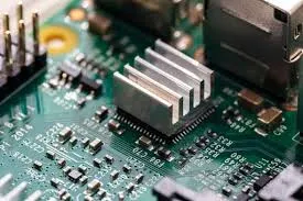
3. Integrate Heat Sinks for High-Power Components
Heat sinks are a go-to solution for managing heat in industrial robotics PCB designs. These metal structures—often aluminum or copper—absorb and dissipate heat away from critical components. For robotics control PCBs, attach heat sinks to power transistors or ICs generating over 1-2 watts of heat. Choose a heat sink with a thermal resistance of less than 5°C/W for demanding applications. To enhance performance, apply a thin layer of thermal interface material (TIM) with a thermal conductivity of at least 1.5 W/m·K between the component and heat sink, ensuring efficient heat transfer.
4. Select High-Temperature PCB Materials
Standard FR-4 PCB materials may not withstand the extreme conditions of harsh environments, with a typical glass transition temperature (Tg) of 130-140°C. For high-temperature PCB designs in robotics, opt for advanced materials like polyimide or high-Tg FR-4, which offer Tg values of 170-250°C and better thermal stability. These materials resist degradation at elevated temperatures and maintain structural integrity under thermal cycling. While they may cost 20-30% more than standard options, the investment pays off in reliability for industrial robotics PCB applications.
5. Use Copper Planes and Pours for Passive Cooling
Large copper planes or pours act as passive heat spreaders, distributing thermal energy across the PCB surface. In multilayer boards, dedicate inner layers to solid copper ground or power planes to maximize heat dissipation. For surface layers, add copper pours around heat-generating components, ensuring at least 2 oz/ft2 copper weight for better thermal conductivity. This technique can lower local temperatures by 5-10°C, making it a cost-effective solution for PCB heat dissipation in robotics systems.
6. Incorporate Active Cooling Solutions When Necessary
In extreme cases where passive cooling isn’t enough, active cooling methods like fans or Peltier coolers can be integrated into robotics control PCB designs. Small, low-power fans with airflow ratings of 10-20 CFM (cubic feet per minute) can be mounted near high-heat areas to force air circulation. Ensure the fan’s power draw—typically 0.5-1.5 watts—doesn’t strain the system’s power budget. While active cooling adds complexity and cost, it’s invaluable for robotics operating in environments above 70°C ambient temperature.
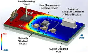
7. Simulate and Test Thermal Performance Early
Before finalizing a design, use thermal simulation software to predict heat distribution and identify potential hotspots. Tools can model temperature rises under various loads, helping you adjust layouts or add cooling features proactively. For instance, simulations might reveal a component reaching 150°C under a 5-watt load, prompting the addition of thermal vias or a heat sink. Post-prototype, conduct real-world testing in conditions mimicking the target environment—such as 85°C for 24 hours—to validate your robotics PCB thermal design.
Special Considerations for Harsh Environments
Harsh environments demand extra attention beyond standard thermal management. Dust and debris can clog heat sinks or fans, reducing their effectiveness, so consider sealed enclosures with passive cooling fins. Humidity can cause condensation on cold components, risking short circuits, so use conformal coatings with thermal conductivity to protect the board while aiding heat transfer. For thermal cycling, select components with matched coefficients of thermal expansion (CTE) to minimize mechanical stress—aim for a CTE difference of less than 10 ppm/°C between the PCB and mounted parts.
Case Study: Thermal Design for an Industrial Robotics Arm
Consider a robotics arm used in a factory with ambient temperatures of 60-80°C. The control PCB, handling 10 watts of power through its motor drivers, faced overheating issues, with junction temperatures hitting 140°C. Designers implemented a multi-layer board with 2 oz/ft2 copper planes, added a grid of 0.4 mm thermal vias under the drivers, and attached aluminum heat sinks with a thermal resistance of 4°C/W. They also switched to a high-Tg FR-4 material (Tg 170°C). Post-implementation, junction temperatures dropped to 110°C, well within safe limits, and the system operated reliably for over 5,000 hours of testing.
Benefits of Proper Thermal Management in Robotics PCBs
Investing in robust thermal management for robotics control PCBs yields significant advantages. First, it enhances reliability, reducing failure rates by up to 50% in high-temperature environments. Second, it extends component lifespan, cutting maintenance costs. Third, it ensures consistent performance, critical for precision tasks in industrial robotics. Finally, effective heat dissipation prevents thermal throttling, maintaining processing speeds even under heavy loads—vital for real-time control systems.
Common Mistakes to Avoid in Robotics PCB Thermal Design
Even experienced designers can overlook key aspects of thermal management. One common error is underestimating ambient temperatures, leading to insufficient cooling. Always design for worst-case scenarios, adding a 10-20°C buffer to expected conditions. Another mistake is neglecting thermal vias’ placement—random or sparse vias won’t transfer heat effectively. Also, avoid using low-quality thermal interface materials; a conductivity below 1 W/m·K can bottleneck heat transfer. Lastly, skipping simulations can result in costly redesigns, so prioritize early thermal analysis.
Future Trends in Thermal Management for Robotics PCBs
As robotics systems grow more powerful and compact, thermal challenges will intensify. Emerging solutions include advanced materials like graphene-based thermal films, offering conductivity up to 5,000 W/m·K, far surpassing traditional options. Liquid cooling, though complex, is gaining traction for ultra-high-power robotics, with microchannel heat exchangers reducing temperatures by 20-30°C in tight spaces. Additionally, AI-driven design tools are optimizing layouts for heat dissipation, predicting thermal behavior with 90% accuracy before prototyping. Staying ahead of these trends can give your industrial robotics PCB designs a competitive edge.
Conclusion: Building Resilient Robotics PCBs for Harsh Conditions
Thermal management is a cornerstone of reliable robotics control PCBs, especially in harsh environments. By optimizing layouts, using thermal vias, integrating heat sinks, selecting high-temperature PCB materials, and testing designs thoroughly, you can ensure your boards withstand extreme conditions without compromising performance. Whether you’re designing for industrial robotics or outdoor automation, these strategies for PCB heat dissipation provide a roadmap to success. Implement them in your next project to achieve durability, efficiency, and longevity, keeping your robotics systems running smoothly no matter the challenge.


