 ALLPCB


In the demanding world of military radar systems, high-power printed circuit boards (PCBs) face extreme challenges in managing heat. Effective thermal management is critical to ensure reliability, performance, and longevity of these systems in harsh environments. This blog dives deep into proven strategies like PCB thermal vias, heat sink design for PCBs, thermal simulation for PCB designs, metal core PCB applications in radar, and high-power PCB cooling techniques. Whether you're designing for aerospace or defense applications, these methods will help you tackle heat dissipation efficiently.
Below, we explore each strategy in detail, providing practical insights and actionable tips to optimize thermal performance for military radar PCBs.
Why Thermal Management Matters for Military Radar PCBs
Military radar systems operate under intense conditions, often generating significant heat due to high power densities. Without proper thermal management, excessive heat can lead to component failure, signal distortion, and reduced system reliability. For instance, radar systems may handle power levels exceeding 100 watts per square inch, with operating temperatures needing to stay below 85°C for optimal performance. Failing to manage heat can result in thermal runaway, where components overheat and degrade rapidly.
In military applications, reliability is non-negotiable. A single failure in a radar PCB can compromise mission success. Therefore, implementing robust thermal management strategies is essential to maintain performance in extreme temperatures, high altitudes, and rugged environments.
Key Thermal Management Strategies for High-Power Radar PCBs
1. Utilizing PCB Thermal Vias for Efficient Heat Dissipation
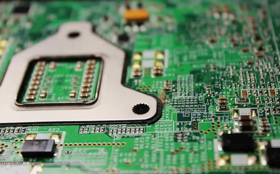
PCB thermal vias are small, conductive pathways that transfer heat from the top layer of a PCB to the bottom or internal layers, where it can dissipate more effectively. In high-power military radar PCBs, thermal vias are indispensable for managing localized heat generated by power amplifiers and other high-energy components.
For optimal performance, thermal vias should be placed directly beneath heat-generating components. A common practice is to use an array of vias with a diameter of 0.3 to 0.5 mm, spaced at 1.0 to 1.5 mm intervals. Copper-filled vias are often preferred due to their high thermal conductivity of approximately 400 W/m·K, compared to standard vias that may only achieve 50-100 W/m·K with partial fill materials.
However, overusing vias can weaken the board's structural integrity or interfere with signal routing. Balancing thermal performance with mechanical and electrical requirements is key. Designers should also ensure vias connect to large copper planes or heat sinks on the opposite side of the board to maximize heat transfer.
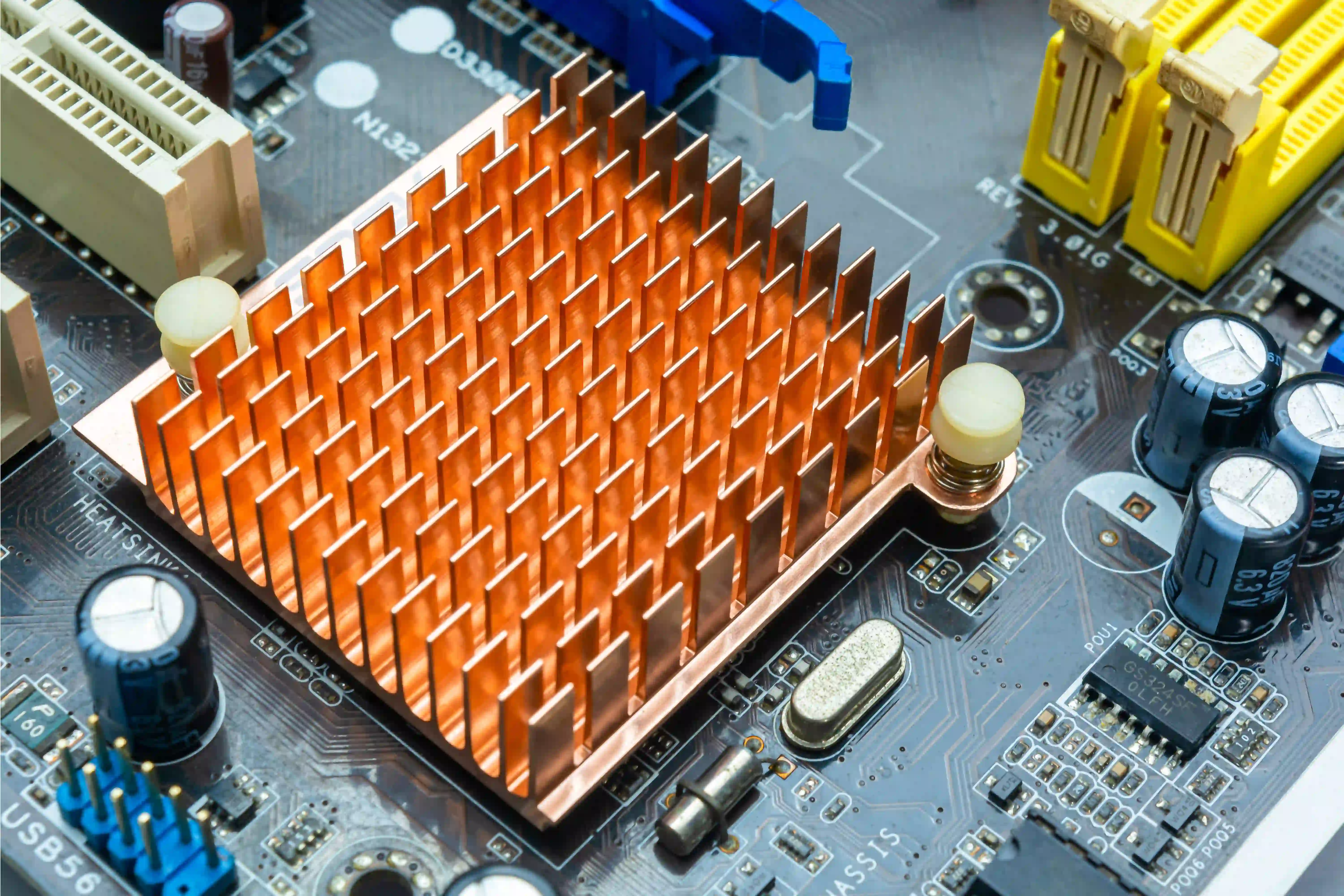
2. Heat Sink Design for PCBs: Enhancing Cooling Capacity
Heat sinks are a cornerstone of thermal management in high-power PCB designs. For military radar systems, where space and weight are often constrained, heat sink design must balance efficiency with compactness. Heat sinks work by increasing the surface area available for heat dissipation, often using materials like aluminum (thermal conductivity of 205 W/m·K) or copper (400 W/m·K).
In radar applications, forced convection heat sinks with integrated fans or liquid cooling channels are common due to the high heat loads, which can exceed 200 watts per component. For instance, a finned heat sink with a base thickness of 3-5 mm and fin heights of 10-20 mm can effectively dissipate heat in confined spaces. The design should ensure tight thermal contact with the PCB, often achieved using thermal interface materials (TIMs) with conductivity values of 1-5 W/m·K to minimize thermal resistance.
Placement is critical—heat sinks should be positioned over the hottest components, such as RF power amplifiers, with airflow directed to avoid hot spots. In military environments, where systems may operate in dusty or humid conditions, sealed or ruggedized heat sinks are often necessary to prevent contamination.
3. Thermal Simulation for PCB Design: Predicting and Preventing Issues
Thermal simulation for PCB designs is a powerful tool to predict heat distribution and identify potential problem areas before manufacturing. In military radar systems, where redesigns are costly and time-sensitive, simulation ensures that thermal management strategies work effectively under real-world conditions.
Using software tools, engineers can model heat flow, component temperatures, and airflow dynamics. For example, simulations might reveal that a specific power transistor reaches 120°C under full load, exceeding its safe operating limit of 100°C. This insight allows designers to adjust via placement, add heat sinks, or modify board layout early in the design phase.
Key parameters in thermal simulation include ambient temperature (often set to 50°C or higher for military environments), power dissipation (e.g., 50-500 watts depending on the radar module), and material properties like thermal conductivity and specific heat capacity. Accurate simulations reduce prototyping costs and ensure compliance with military standards like MIL-STD-810 for environmental testing.
4. Metal Core PCB for Radar Applications: Built-In Heat Management
Metal core PCBs (MCPCBs) are specially designed boards with a metal base layer, typically aluminum or copper, to enhance heat dissipation. For military radar systems, metal core PCB radar designs are ideal because they handle high power densities while maintaining structural integrity in extreme conditions.
The metal core acts as a built-in heat spreader, with thermal conductivity values ranging from 1 to 4 W/m·K for aluminum-based MCPCBs, significantly higher than traditional FR-4 materials (0.3 W/m·K). This allows heat to spread evenly across the board, reducing hot spots near high-power components like transmitters or processors.
In practice, MCPCBs are often used in radar power modules, where heat loads can exceed 300 watts. The dielectric layer between the metal core and copper traces must be carefully selected for thermal performance and electrical insulation, typically with a thickness of 0.1 to 0.2 mm to minimize thermal resistance. While MCPCBs are more expensive than standard boards, their ability to handle heat makes them a worthwhile investment for military applications.
5. High-Power PCB Cooling Techniques: Advanced Solutions
Beyond vias, heat sinks, and metal cores, advanced high-power PCB cooling techniques are often necessary for military radar systems. These systems may require innovative approaches to manage heat loads that exceed 500 watts across the board.
Liquid Cooling: Liquid cooling systems use coolant fluids circulated through microchannels or tubes embedded near the PCB. With a heat transfer coefficient up to 10 times higher than air cooling, liquid cooling can maintain component temperatures below 60°C even under extreme loads. This method is often used in compact radar systems where space for large heat sinks is limited.
Phase-Change Materials (PCMs): PCMs absorb heat by changing phase (e.g., from solid to liquid) at specific temperatures. They are useful in military applications for temporary heat storage during peak loads, with capacities to absorb up to 200 J/g of heat. PCMs can be integrated near critical components to delay temperature spikes.
Forced Air Systems: High-velocity fans or blowers direct air over heat sinks or exposed PCB areas. In military radar, ruggedized fans with airflow rates of 50-100 cubic feet per minute (CFM) are common to ensure consistent cooling in harsh environments.
Each cooling method has trade-offs in terms of weight, cost, and complexity. Designers must evaluate mission requirements, such as operating temperature ranges from -40°C to 85°C, to select the most effective solution.
Best Practices for Implementing Thermal Management in Military Radar PCBs
To achieve optimal thermal performance, consider the following best practices during the design and manufacturing process:
- Material Selection: Choose substrates and laminates with high thermal conductivity, such as ceramic-filled materials or metal core options, to enhance heat dissipation.
- Component Placement: Position high-power components away from each other to avoid concentrated heat zones. Use thermal simulations to validate placement.
- Layer Stack-Up: Design multi-layer boards with dedicated ground and power planes to act as heat spreaders, connecting them to thermal vias for maximum effect.
- Environmental Testing: Test designs under simulated military conditions, including temperature cycling from -55°C to 125°C, to ensure reliability per MIL-STD-810 standards.
- Collaboration: Work closely with manufacturing partners to ensure design specifications for thermal vias, heat sinks, and cooling systems are feasible and cost-effective.
Challenges in Thermal Management for Military Radar PCBs
Despite the effectiveness of these strategies, challenges remain. Military radar systems often operate in confined spaces with limited airflow, making passive cooling less effective. Additionally, the push for miniaturization increases power density, with some modern radar modules packing over 1 kW of power into a few square inches. Balancing thermal performance with size, weight, and power (SWaP) constraints requires innovative design and materials.
Another challenge is the harsh operating environment. Military radar PCBs must withstand vibration, shock, and humidity while maintaining thermal stability. This often necessitates ruggedized cooling solutions that add weight or complexity to the system.
Conclusion: Building Reliable Radar Systems with Effective Thermal Management
Thermal management is a critical factor in the design of high-power military radar PCBs. By leveraging strategies like PCB thermal vias, optimized heat sink design for PCBs, thermal simulation for PCB layouts, metal core PCB radar solutions, and advanced high-power PCB cooling techniques, engineers can ensure reliable performance under the toughest conditions. Each method offers unique benefits, from the simplicity of thermal vias to the high efficiency of liquid cooling, allowing designers to tailor solutions to specific mission needs.
At ALLPCB, we understand the importance of thermal management in military applications. Our expertise in advanced PCB design and manufacturing helps engineers overcome heat-related challenges with precision and reliability. By applying the strategies outlined in this blog, you can build radar systems that stand up to the demands of modern defense technology.


