 ALLPCB


In the challenging environment of space, managing heat in high-density spacecraft electronics PCBs (Printed Circuit Boards) is critical for ensuring reliability and performance. With electronics packed tightly into compact designs, heat buildup can lead to component failure, reduced lifespan, and mission-critical issues. So, how can engineers tackle these thermal challenges? The answer lies in strategic PCB thermal design for space, incorporating techniques like thermal vias in spacecraft PCBs, advanced heat dissipation methods, thorough thermal analysis of PCB layouts, and optimized component placement for thermal management.
In this comprehensive guide, we'll dive deep into effective thermal management strategies tailored for spacecraft electronics. Whether you're an aerospace engineer or a PCB designer, you'll find practical tips and insights to help you design boards that withstand the harsh conditions of space while maintaining optimal performance.
Why Thermal Management is Critical for Spacecraft Electronics PCBs
Spacecraft operate in a vacuum where there is no air to conduct heat away from electronics. This makes thermal management a unique challenge compared to terrestrial applications. High-density PCBs in spacecraft often power critical systems like communication, navigation, and data processing, generating significant heat in a confined space. Without proper heat dissipation techniques for PCBs, temperatures can soar beyond safe limits, often exceeding 125°C for some components, leading to thermal stress and potential failure.
Additionally, the extreme temperature swings in space—ranging from -150°C in shadow to over 120°C in direct sunlight—compound the problem. Effective thermal management ensures that components stay within their operational range, typically between -40°C and 85°C for most aerospace-grade electronics, preserving mission integrity.
Key Challenges in PCB Thermal Design for Space
Designing PCBs for space applications involves addressing several unique challenges:
- High Power Density: Modern spacecraft electronics often pack high-performance chips into small areas, leading to power densities exceeding 10 W/cm2 in some cases, which generates substantial heat.
- Limited Cooling Options: Unlike ground-based systems, there are no fans or convection currents in space. Heat must be managed through conduction and radiation.
- Material Constraints: Materials must withstand radiation, outgassing, and extreme temperatures while providing good thermal conductivity.
- Weight and Size Limits: Every gram counts in spacecraft design, so thermal solutions must be lightweight and compact.
Addressing these challenges requires a multi-faceted approach, combining innovative design techniques with advanced materials and precise analysis.
Related Reading: Thermal Management in PCB Design: Meeting Standards for Heat Dissipation
Effective Thermal Management Strategies for Spacecraft PCBs
Let’s explore proven strategies for managing heat in high-density spacecraft electronics PCBs. These methods focus on design, materials, and analysis to ensure optimal performance in the harsh space environment.
1. Optimize PCB Thermal Design for Space with Material Selection
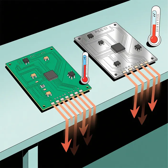
The choice of materials plays a huge role in managing heat. Standard FR-4 materials, with a thermal conductivity of about 0.3 W/m·K, are often insufficient for high-density spacecraft PCBs. Instead, consider these alternatives:
- High Thermal Conductivity Laminates: Materials like polyimide or ceramic-based substrates offer thermal conductivities up to 1.5 W/m·K or higher, improving heat transfer.
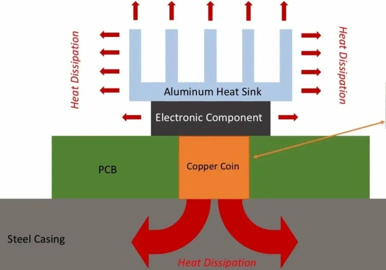
- Metal-Core PCBs: Using aluminum or copper cores with thermal conductivities of 200 W/m·K or more can significantly enhance heat dissipation.
- Thermal Interface Materials (TIMs): TIMs with conductivities around 5-10 W/m·K can bridge gaps between components and heat sinks, ensuring efficient heat transfer.
Selecting materials that balance thermal performance with weight and durability is essential for space applications.
Related Reading: FR-4 PCB Thermal Management: Strategies for High-Power Applications
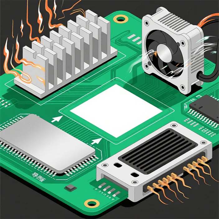
2. Utilize Thermal Vias in Spacecraft PCBs
Thermal vias are small holes filled or plated with conductive material, typically copper, that transfer heat from one layer of the PCB to another or to a heat sink. In spacecraft PCBs, thermal vias are indispensable for managing heat in multi-layer, high-density designs.
- Placement: Position thermal vias directly under heat-generating components like power ICs or processors to create a direct path for heat to escape.
- Density and Size: Use an array of vias with diameters around 0.3-0.5 mm. Studies suggest that a via density of 25-30 vias per square centimeter under hot components can reduce temperatures by up to 10-15°C.
- Material: Copper-filled vias offer the best thermal conductivity, often around 400 W/m·K, compared to unfilled or epoxy-filled vias.
By integrating thermal vias in spacecraft PCBs, designers can effectively channel heat away from critical components, preventing hotspots that could degrade performance.
3. Implement Heat Dissipation Techniques for PCBs
Since convection cooling isn’t an option in space, heat dissipation in spacecraft PCBs relies on conduction and radiation. Here are some effective techniques:
- Heat Sinks and Spreaders: Attach lightweight heat sinks made of aluminum (thermal conductivity ~200 W/m·K) to high-power components. Heat spreaders can distribute heat evenly across the board, reducing localized hotspots.
- Copper Planes: Dedicate entire layers or large areas of the PCB to thick copper planes (e.g., 2 oz or 70 μm thick) to act as thermal conduits, spreading heat across the board.
- Radiative Surfaces: Coat PCB surfaces or enclosures with high-emissivity materials (emissivity >0.8) to enhance radiative heat loss into space.
These heat dissipation techniques for PCBs are often combined to maximize thermal performance while adhering to strict weight and size constraints in spacecraft design.
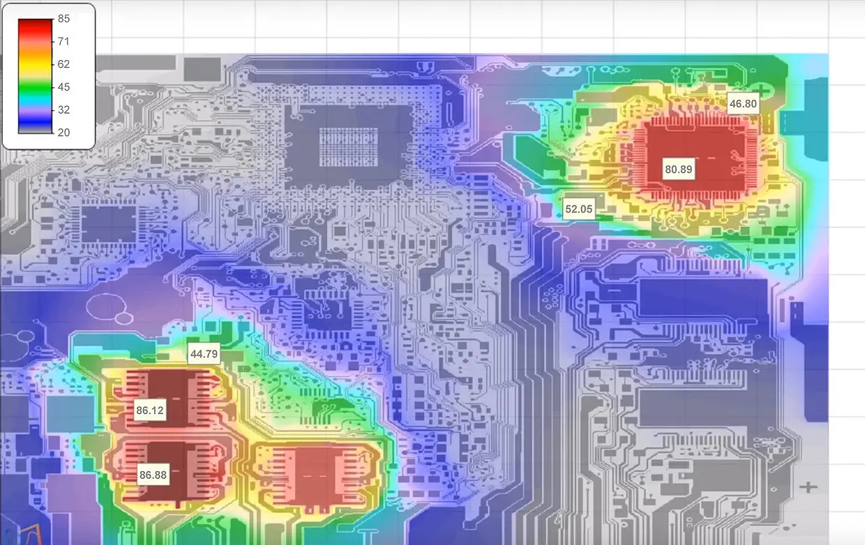
4. Conduct Thorough Thermal Analysis of PCB Layouts
Thermal analysis of PCB designs is a critical step to predict and mitigate heat-related issues before manufacturing. Advanced simulation tools can model heat flow and identify potential problem areas in high-density designs.
- Finite Element Analysis (FEA): Use FEA to simulate temperature distribution across the PCB under various operating conditions. This can predict temperature rises, often within ±2°C accuracy, for components generating 5-10 W of heat.
- Hotspot Identification: Identify areas where temperatures exceed safe limits, such as above 85°C for standard components, and adjust the design accordingly.
- Environmental Modeling: Factor in space-specific conditions like solar radiation (up to 1,400 W/m2) and vacuum conditions to ensure realistic results.
By performing a detailed thermal analysis of PCB layouts, engineers can make data-driven decisions to optimize heat management and prevent failures during missions.
5. Strategic Component Placement for Thermal Management
The arrangement of components on a PCB directly impacts thermal performance. Thoughtful component placement for thermal management can prevent heat buildup and improve overall reliability.
- Spacing: Avoid clustering high-power components together. Distribute heat sources evenly across the board to prevent concentrated hotspots. Maintain at least 5-10 mm spacing between power-intensive parts if possible.
- Proximity to Heat Sinks: Place high-heat components near thermal vias or heat sinks to facilitate quick heat transfer.
- Orientation: Align components to optimize heat flow toward radiative surfaces or conductive paths. For instance, position power transistors perpendicular to copper planes for better heat spreading.
Strategic component placement for thermal management ensures that heat is distributed evenly, reducing the risk of thermal stress on sensitive electronics.
Best Practices for Implementing Thermal Management in Spacecraft PCBs
Beyond specific strategies, following these best practices can further enhance thermal performance in high-density spacecraft electronics:
- Iterative Design: Use multiple design iterations with thermal simulations to refine layouts and material choices. Even small changes, like adjusting via placement, can lower temperatures by 5-10°C.
- Lightweight Solutions: Prioritize low-weight materials and designs, as every additional gram increases launch costs significantly, often by thousands of dollars per kilogram.
- Compliance with Standards: Adhere to aerospace standards like those from ECSS (European Cooperation for Space Standardization) for material selection and thermal design to ensure reliability.
- Testing: Conduct thermal vacuum testing to replicate space conditions, ensuring the PCB can handle temperature extremes and heat loads without failure.
Case Study: Thermal Management in a Satellite Communication PCB
Consider a hypothetical satellite communication module with a high-density PCB powering a 10 W RF amplifier. Without proper thermal management, the amplifier’s junction temperature could reach 150°C, far above its safe limit of 100°C. By implementing a combination of thermal vias (30 vias under the amplifier), a 1 oz copper plane for heat spreading, and a small aluminum heat sink, the temperature was reduced to 90°C during simulations. Adding a high-emissivity coating further lowered it to 85°C by enhancing radiative cooling. This example shows how combining multiple strategies can achieve significant thermal improvements.
Conclusion: Building Reliable Spacecraft Electronics with Effective Thermal Management
Thermal management is a cornerstone of designing high-density spacecraft electronics PCBs. By focusing on PCB thermal design for space, integrating thermal vias in spacecraft PCBs, employing heat dissipation techniques for PCBs, conducting detailed thermal analysis of PCB layouts, and optimizing component placement for thermal management, engineers can create boards that perform reliably in the extreme conditions of space.
At ALLPCB, we understand the unique challenges of aerospace applications and are committed to supporting designers with high-quality manufacturing solutions tailored for thermal performance. Whether you’re working on a small satellite or a complex spacecraft system, these strategies can help you manage heat effectively and ensure mission success.
Start implementing these thermal management techniques in your next project to build robust, high-performing PCBs that stand up to the rigors of space. With the right approach, you can keep your electronics cool, even in the vacuum of space.


