ALLPCB


If you're looking to replace components on an ECU PCB (Engine Control Unit Printed Circuit Board), you've come to the right place. Whether it's a damaged capacitor, a faulty resistor, or a worn-out microcontroller, this guide will walk you through the process of ECU PCB component replacement with clear, actionable steps. We'll cover everything from desoldering techniques to soldering methods for both SMD (Surface-Mount Device) and through-hole components. Let's dive into the detailed process to ensure your repair is successful and your vehicle's brain is back in top shape.
What Is an ECU PCB and Why Replace Components?
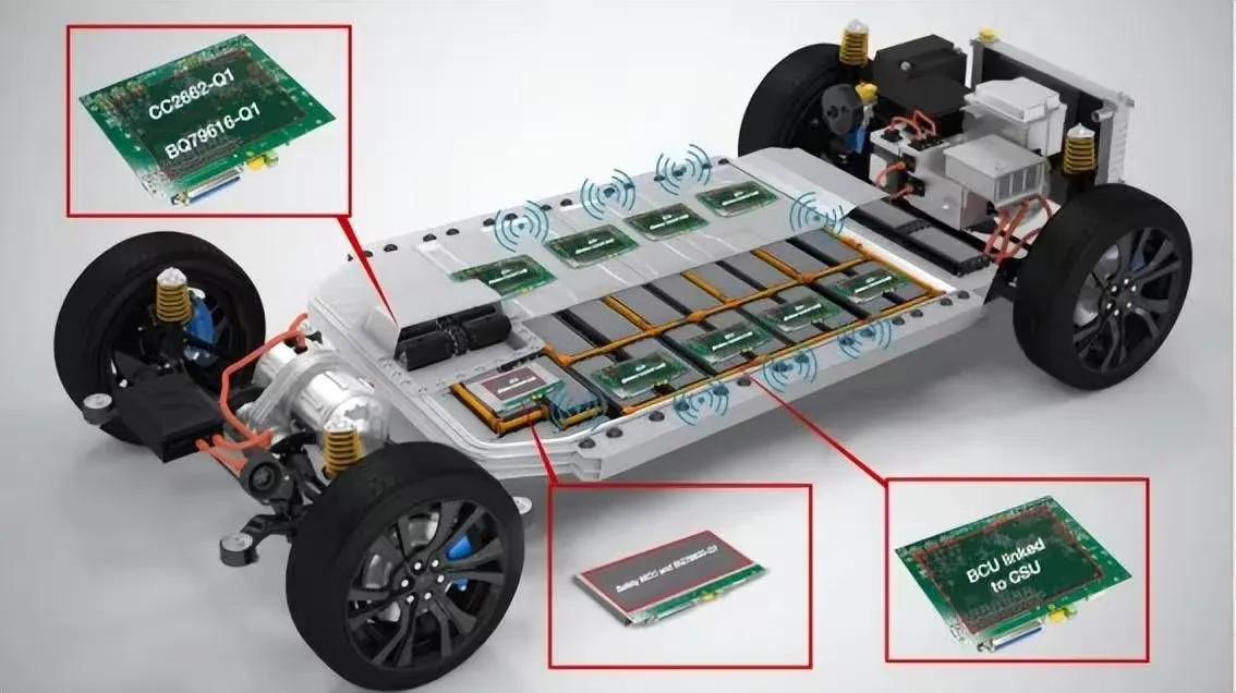
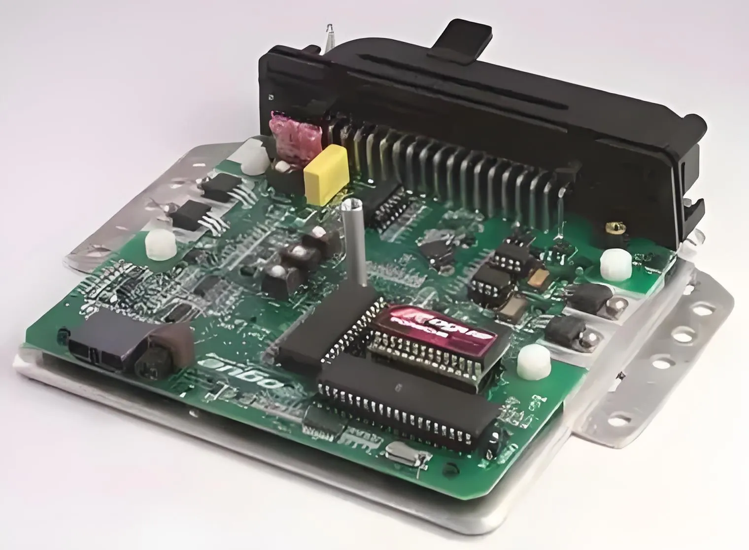
An ECU PCB is the core of a vehicle's electronic control system, managing critical functions like fuel injection, ignition timing, and emission controls. Over time, components on the PCB can fail due to heat, vibration, or electrical surges, leading to issues like engine misfires or complete system failure. Replacing these components can save you from the high cost of a full ECU replacement, often ranging from $500 to $1500, depending on the vehicle model.
In this guide, we'll focus on practical steps for SMD component replacement and through-hole component replacement, along with essential soldering and desoldering techniques. Whether you're a hobbyist or a professional technician, these steps will help you tackle the repair with confidence.
Tools and Materials Needed for ECU PCB Component Replacement
Before starting, gather the right tools and materials to ensure a smooth process. Here's a list of essentials for replacing components on an ECU PCB:
- Soldering Iron: A temperature-controlled iron with a fine tip (15-30W for delicate work).
- Desoldering Tools: Desoldering pump, desoldering braid (wick), or a hot air rework station for SMD components.
- Replacement Components: Ensure they match the specifications of the originals (e.g., capacitance, voltage rating, resistance).
- Multimeter: To test continuity and verify component functionality before and after replacement.
- Tweezers: Precision tweezers for handling small SMD components.
- Flux: To improve solder flow and prevent oxidation during soldering.
- Solder Wire: Lead-free solder with a diameter of 0.5-0.8mm for precise work.
- Isopropyl Alcohol and Brush: For cleaning the PCB after soldering or desoldering.
- Magnifying Glass or Microscope: To inspect tiny SMD components and solder joints.
- Anti-static Wrist Strap: To prevent electrostatic discharge (ESD) damage to sensitive components.
Having these tools ready will make the process of ECU PCB component replacement safer and more efficient.
Step 1: Preparation and Safety Measures
Start by setting up a clean, well-lit workspace. ECU PCBs are sensitive to static electricity, so always wear an anti-static wrist strap connected to a grounded surface. Disconnect the vehicle's battery to avoid any accidental power surges while working on the ECU.
Next, identify the faulty component using a multimeter or diagnostic tool. For example, a capacitor with a bulging top or a resistor showing infinite resistance (open circuit) needs replacement. Document the component's location and specifications (e.g., a 10μF capacitor rated at 25V) before proceeding.
Step 2: Desoldering Techniques for Component Removal
Removing the faulty component is a critical step in ECU PCB component replacement. The technique depends on whether you're dealing with SMD or through-hole components. Below, we'll cover desoldering techniques for both.
Desoldering Through-Hole Components
Through-hole components have leads that pass through holes in the PCB and are soldered on the opposite side. To remove them:
- Heat the solder joint on the underside of the PCB with your soldering iron (set to around 300°C).
- Once the solder melts, use a desoldering pump to suck up the molten solder. Press the pump's plunger, place the nozzle over the joint, and release the plunger to remove the solder.
- Alternatively, use desoldering braid by placing it over the joint, heating it with the iron, and letting the braid absorb the solder.
- Once the solder is removed, gently wiggle the component free with tweezers or pliers. If it’s stuck, reheat the joint to ensure all solder is cleared.
Desoldering SMD Components
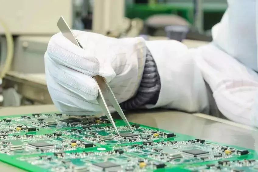
SMD components are soldered directly onto the PCB surface, making them trickier to remove. Use these steps for SMD component replacement:
- For small SMD parts (like resistors or capacitors), apply flux to the solder joints to improve heat transfer.
- Use a hot air rework station set to 300-350°C. Direct the hot air over the component until the solder melts (usually 10-15 seconds).
- Use tweezers to lift the component off the board. Avoid excessive heat, as it can damage nearby components or lift PCB traces.
- For larger SMD components (like IC chips), heat all pins simultaneously with the hot air station and lift the component once the solder melts.
After removal, clean the pads with isopropyl alcohol and a brush to remove leftover solder or flux residue.
Step 3: Preparing the PCB for New Components
With the old component removed, inspect the PCB pads or holes for damage. If a pad is lifted or a trace is broken, you may need to repair it using a conductive pen or jumper wire before proceeding. Use a multimeter to check for continuity between pads and nearby traces to ensure no shorts exist.
For through-hole components, ensure the holes are clear of old solder. If necessary, use a desoldering pump or drill bit (manually) to clean them out. For SMD pads, apply a thin layer of flux to help the new solder adhere properly.
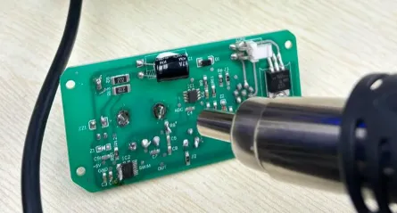
Step 4: Soldering Techniques for Component Installation
Now it's time to install the replacement component. Proper soldering techniques are crucial to avoid cold joints or damage to the ECU PCB.
Soldering Through-Hole Components
- Insert the new component into the holes, ensuring correct orientation (e.g., polarity for capacitors or diodes).
- Bend the leads slightly on the underside to hold the component in place.
- Apply flux to the leads and pads for better solder flow.
- Heat the pad and lead with your soldering iron (300°C) for 2-3 seconds, then apply solder wire to the joint until it flows evenly around the lead.
- Remove the iron and let the joint cool naturally. Avoid blowing on it, as this can cause cracks in the solder.
- Trim excess leads with flush cutters.
Soldering SMD Components
- Place a small amount of solder on one of the PCB pads using your soldering iron.
- Position the SMD component on the pads using tweezers, aligning it with the pre-soldered pad.
- Heat the pre-soldered pad to attach the component, then solder the remaining pads by applying solder and flux.
- For IC chips with multiple pins, use a drag soldering technique: apply flux, place a bead of solder across all pins, and use the iron tip to distribute it evenly. Remove excess solder with desoldering braid if needed.
After soldering, inspect the joints under a magnifying glass. A good joint should be shiny and concave, not dull or blobby, which indicates a cold joint.

Step 5: Testing and Verification
Once the new component is soldered in place, test the ECU PCB to ensure functionality. Use a multimeter to check for proper resistance, capacitance, or voltage values based on the component's specifications. For example, a replaced 1kΩ resistor should read close to 1000 ohms on the multimeter.
Reinstall the ECU in the vehicle and reconnect the battery. Start the engine and monitor for error codes using an OBD-II scanner. If the issue persists, double-check your solder joints or verify that the replacement component matches the original specs.
Common Challenges and Tips for ECU PCB Component Replacement
Replacing components on an ECU PCB can come with challenges. Here are some common issues and tips to overcome them:
- Overheating Components: Limit soldering iron contact to 3-5 seconds per joint to prevent heat damage. For SMD components, keep hot air exposure under 20 seconds.
- Lifted Pads: If a pad lifts during desoldering, use a small jumper wire to reconnect it to the trace.
- Component Polarity: Always double-check polarity for components like diodes and electrolytic capacitors. Incorrect orientation can cause circuit failure.
- Cold Solder Joints: If a joint looks dull or cracked, reheat it and add fresh solder to ensure a strong connection.
Why Choose Professional Help for Complex Repairs?
While DIY ECU PCB component replacement is cost-effective, complex repairs involving microcontrollers or multilayer boards may require professional expertise. Specialized technicians have access to advanced tools like X-ray inspection for hidden solder issues and can reprogram ECUs if firmware corruption occurs during repair.
If you're unsure about a repair, consider consulting a professional to avoid further damage to the ECU, which could lead to costly replacements.
Conclusion: Mastering ECU PCB Component Replacement
Replacing components on an ECU PCB is a rewarding skill that can save you significant repair costs. By following this step-by-step guide, you've learned essential desoldering techniques and soldering techniques for both SMD component replacement and through-hole component replacement. From preparing your workspace to testing the repaired ECU, each step is designed to help you achieve a successful outcome.
Remember to work patiently, use the right tools, and double-check your solder joints and component specs. With practice, you'll gain confidence in tackling ECU PCB repairs and keep your vehicle's electronics running smoothly.