 ALLPCB


If you're looking to build or repair a security camera by soldering and assembling its PCB (Printed Circuit Board), you're in the right place. This guide offers a step-by-step approach to security camera PCB soldering and CCTV PCB assembly, helping you create a functional and reliable surveillance system. Whether you're a hobbyist or a professional, we'll walk you through the process with clear instructions and practical tips.
In this detailed tutorial, we'll cover everything from the tools you need for soldering components onto a camera PCB to best practices for assembling the board. You'll also find actionable DIY electronics assembly guide tips and security camera PCB building tips to ensure your project succeeds. Let's dive into the world of camera PCB assembly and get started!
Why Build or Repair a Security Camera PCB?
Security cameras are essential for monitoring homes, offices, and public spaces. While pre-built cameras are widely available, assembling or repairing a PCB for a CCTV system offers several advantages. It allows for customization, cost savings, and a deeper understanding of how these devices work. By mastering security camera PCB soldering, you can tailor the camera's features, such as resolution or night vision capabilities, to your specific needs.
Beyond customization, working on a CCTV PCB assembly tutorial project helps you develop valuable skills in electronics. Whether you're replacing a faulty component or building a camera from scratch, this guide will equip you with the knowledge to handle the task confidently.
Tools and Materials Needed for Security Camera PCB Soldering
Before you start soldering or assembling, gather the necessary tools and materials. Having everything ready will make the process smoother and prevent interruptions. Here's a list of essentials for soldering components onto a camera PCB:
- Soldering Iron: Use a temperature-controlled soldering iron with a fine tip (around 1mm) for precision. A 25-40 watt iron is ideal for PCB work.
- Solder Wire: Choose a lead-free solder wire with a rosin core, typically 0.8mm to 1mm in diameter, for clean joints.
- Desoldering Tools: A desoldering pump or wick is useful for correcting mistakes or removing old components.
- Flux: Apply flux to improve solder flow and ensure strong connections on the PCB.
- Multimeter: Essential for testing connections and verifying voltages (e.g., ensuring a 12V DC input for most security cameras).
- Tweezers: Precision tweezers help place small components like resistors or capacitors on the board.
- Magnifying Glass or Loupe: Useful for inspecting tiny solder joints and component placements.
- PCB and Components: Ensure you have the correct PCB layout for your security camera and all required components, such as image sensors, resistors, capacitors, and connectors.
- Safety Gear: Wear safety glasses to protect your eyes from solder splashes and use a well-ventilated workspace to avoid inhaling fumes.
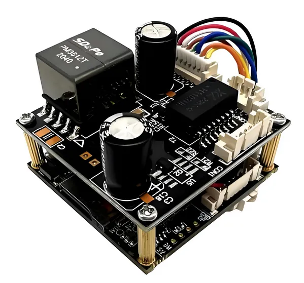
Understanding the Security Camera PCB Layout
Before you begin soldering, familiarize yourself with the PCB layout for your security camera. Most camera PCBs include sections for the image sensor, power supply circuitry, signal processing, and output connectors. Key components often found on a security camera PCB include:
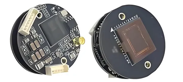
- Image Sensor: The heart of the camera, typically a CMOS or CCD sensor, capturing video data.
- Power Regulation Circuit: Converts input voltage (often 12V DC) to lower voltages (e.g., 3.3V or 5V) for various components.
- Signal Processing Chip: Processes raw data from the sensor into a usable video signal.
- Connectors: Ports for power input, video output (e.g., BNC or RCA), and sometimes network connectivity for IP cameras.
Study the schematic or diagram provided with your PCB to identify where each component belongs. If you're designing a custom board, ensure the impedance of traces matches the requirements (e.g., 75 ohms for video signal lines in analog cameras) to avoid signal loss.
Step-by-Step Guide to Soldering Components onto a Camera PCB
Now that you're familiar with the tools and layout, let's walk through the process of soldering components onto a camera PCB. Follow these steps carefully for a successful build.
Step 1: Prepare Your Workspace
Set up a clean, well-lit workspace with proper ventilation. Secure the PCB on a holder or flat surface to prevent movement during soldering. Ensure your soldering iron is heated to the right temperature (around 300°C or 572°F for most components) to avoid damaging the board or components.
Step 2: Start with Low-Profile Components
Begin by soldering smaller, low-profile components like resistors and capacitors. Place each component in its designated spot on the PCB, aligning the leads with the corresponding pads. Apply a small amount of flux to the pads, then touch the soldering iron tip to the pad and lead while feeding solder wire to create a shiny, cone-shaped joint. Avoid applying too much solder, as it can cause shorts.
For example, if you're soldering a 1kΩ resistor for a power regulation circuit, ensure the color bands match the schematic before placement. A typical capacitor on a camera PCB might be a 10μF electrolytic cap for smoothing voltage; make sure to observe polarity when installing.
Step 3: Move to Larger Components
After soldering smaller parts, move to larger components like connectors, ICs (Integrated Circuits), and the image sensor. For surface-mount devices (SMDs), use a hot air rework station or drag soldering technique with flux to attach multiple pins at once. For through-hole components, insert the leads through the holes, solder each pin, and trim excess leads with wire cutters.
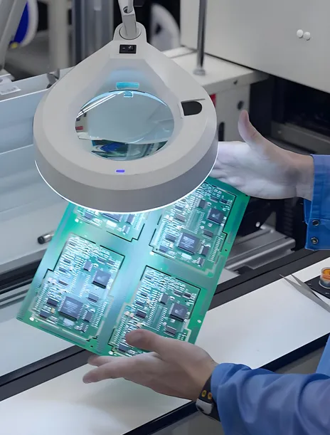
Step 4: Inspect and Clean Solder Joints
Once all components are soldered, inspect each joint under a magnifying glass. Look for cold joints (dull, grainy appearance) or bridges (solder connecting unintended pads). Use a desoldering tool to correct any issues. Clean the PCB with isopropyl alcohol and a brush to remove flux residue, which can cause corrosion over time.
CCTV PCB Assembly Tutorial: Bringing It All Together
With the components soldered, it's time to assemble the PCB into a functional security camera system. Follow these steps for a complete CCTV PCB assembly tutorial.
Step 1: Test the Soldered PCB
Before full assembly, test the PCB to ensure all connections are correct. Use a multimeter to check for continuity between pads and verify power delivery (e.g., 12V at the input and 3.3V at the sensor circuit). Connect a temporary power source and monitor output signals to confirm the board functions as expected.
Step 2: Mount the PCB in the Camera Housing
Secure the PCB inside the camera housing, ensuring no wires or components touch metal parts that could cause shorts. Use standoffs or screws to hold the board in place. Align the image sensor with the lens mount to ensure proper focus and field of view.
Step 3: Connect External Components
Attach the lens to the image sensor mount, and connect power and video output cables to the PCB. For analog cameras, use a BNC connector for video output with a 75-ohm impedance match to prevent signal degradation. For IP cameras, connect an Ethernet cable if applicable.
Step 4: Final Testing and Calibration
Power on the camera and test the video output on a monitor or recording device. Adjust the lens focus if needed to achieve a clear image. Check for issues like flickering or noise, which could indicate a soldering error or power supply problem. If the camera supports infrared (IR) for night vision, test it in low-light conditions to ensure the IR LEDs activate properly.
Security Camera PCB Building Tips for Success
To ensure your project goes smoothly, keep these security camera PCB building tips in mind:
- Double-Check Component Orientation: Pay attention to polarity for components like capacitors and diodes. Incorrect placement can damage the board or prevent the camera from working.
- Avoid Overheating: Limit soldering iron contact to 2-3 seconds per joint to prevent heat damage to components or PCB traces.
- Use Proper Grounding: Ensure the PCB has a solid ground plane to reduce electrical noise, especially important for video signals in security cameras.
- Test Incrementally: Test the board after soldering major sections to catch issues early, rather than waiting until the end.
- Keep Documentation Handy: Refer to the PCB schematic and component datasheets during assembly to avoid mistakes.
Troubleshooting Common Issues in Security Camera PCB Assembly
Even with careful work, problems can arise during DIY electronics assembly guide projects. Here are solutions to common issues:
- No Video Output: Check power connections and ensure the image sensor is properly soldered. Verify output impedance (e.g., 75 ohms for analog video) matches the connected device.
- Poor Image Quality: Inspect the lens for dirt or misalignment. Noise in the image could indicate a grounding issue or interference from nearby circuits.
- Camera Not Powering On: Use a multimeter to confirm input voltage (e.g., 12V DC) reaches the PCB. Look for damaged traces or components in the power circuit.
Conclusion: Mastering Security Camera PCB Soldering and Assembly
Building or repairing a security camera through security camera PCB soldering and assembly is a rewarding project that enhances your electronics skills. By following this CCTV PCB assembly tutorial, you've learned how to solder components, assemble the board, and troubleshoot common issues. With the right tools, patience, and attention to detail, you can create a reliable surveillance system tailored to your needs.
Remember to apply the security camera PCB building tips shared in this guide to avoid mistakes and ensure a professional result. Whether you're a beginner or an experienced hobbyist, this DIY electronics assembly guide provides the foundation for successful camera projects. Start soldering today and take control of your security solutions!


