 ALLPCB


In the harsh environment of space, satellite payload printed circuit boards (PCBs) face intense challenges, particularly from radiation. Radiation can degrade components, disrupt functionality, and ultimately jeopardize mission success. So, how can we ensure reliability in orbit? The answer lies in radiation hardening techniques, which include using radiation-resistant PCB components, mitigating total ionizing dose (TID) effects, employing single event effects (SEE) mitigation strategies, conducting thorough radiation testing for space PCBs, and implementing shielding techniques for satellite electronics. In this comprehensive guide, we'll explore these methods in detail to help engineers design robust satellite systems that withstand the rigors of space.
Understanding the Radiation Challenge in Space
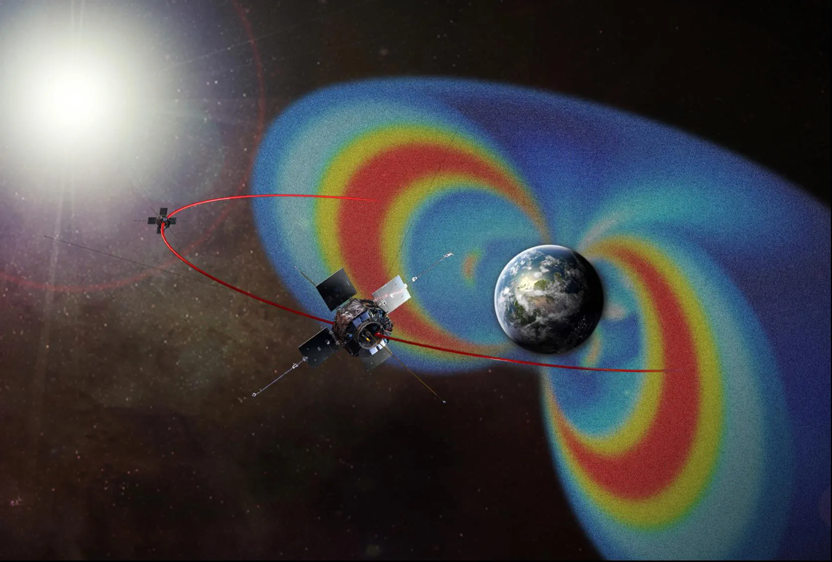
Space is an unforgiving environment for electronics. Beyond Earth's protective atmosphere and magnetic field, satellites are exposed to high levels of ionizing radiation from solar flares, cosmic rays, and trapped particles in radiation belts like the Van Allen belts. This radiation can cause two primary types of damage to PCBs: cumulative effects from total ionizing dose (TID) and instantaneous disruptions from single event effects (SEE). Without proper protection, these can lead to data corruption, system failures, or even complete mission loss. For engineers working on satellite payloads, radiation hardening is not just an option—it's a necessity.
What Is Radiation Hardening for PCBs?
Radiation hardening is the process of designing and manufacturing electronic components and circuits to resist damage or malfunction caused by ionizing radiation. For satellite payload PCBs, this involves a combination of material selection, design strategies, and testing protocols to ensure reliability over long missions, which can last from 5 to 15 years or more. The goal is to protect sensitive electronics from both gradual degradation (TID effects) and sudden failures (SEE), maintaining performance in the extreme conditions of space.
Key Radiation Effects on PCBs
Before diving into hardening techniques, let's break down the two main types of radiation effects on PCBs that engineers must address.
Total Ionizing Dose (TID) Effects on PCBs
TID refers to the cumulative damage caused by prolonged exposure to ionizing radiation. Over time, charged particles can alter the electrical properties of semiconductor materials in PCB components, leading to increased leakage currents, threshold voltage shifts, and reduced performance. For example, a typical satellite in geostationary orbit might experience a TID of 10 to 100 krad (Si) over a 10-year mission, depending on shielding and orbit altitude. Without mitigation, TID effects on PCBs can cause gradual system degradation, eventually leading to failure.
Single Event Effects (SEE) and Their Impact
Unlike TID, SEE are sudden, one-time events caused by a single high-energy particle striking a sensitive area of a component. These can result in temporary disruptions (soft errors) like bit flips in memory or permanent damage (hard errors) such as latch-up, where a component becomes stuck in a high-current state. SEE are particularly dangerous for critical systems in satellite payloads, as a single event can corrupt data or disable control systems in an instant.
Radiation Hardening Techniques for Satellite Payload PCBs
With a clear understanding of the threats, let's explore the practical techniques for radiation hardening. These strategies target both TID effects and SEE, ensuring long-term reliability in orbit.
1. Using Radiation-Resistant PCB Components
The foundation of radiation hardening starts with selecting radiation-resistant PCB components. These are specially designed or selected parts that can withstand higher levels of radiation compared to standard commercial components. For instance, rad-hard microprocessors and memory chips are often fabricated using silicon-on-insulator (SOI) technology, which reduces the volume of material susceptible to radiation-induced charge buildup. Additionally, components are often rated for TID tolerance, with some capable of enduring up to 300 krad (Si) or more.
Engineers should prioritize components with proven space heritage—parts that have been tested and flown in previous missions. When selecting capacitors, resistors, and other passive components, opt for materials less prone to degradation, such as ceramic dielectrics over tantalum in capacitors, as they exhibit better stability under radiation exposure.
2. Design Strategies for SEE Mitigation
While radiation-resistant components help, design-level SEE mitigation strategies are equally critical to protect against sudden failures. Some effective approaches include:
- Triple Modular Redundancy (TMR): This technique involves triplicating critical logic circuits and using a voting system to determine the correct output. If a single event causes an error in one circuit, the other two can override it, ensuring system integrity.
- Error Detection and Correction (EDAC): For memory systems, EDAC codes can detect and correct bit flips caused by SEE. This is especially important for satellite data storage, where corruption can lead to mission-critical errors.
- Guard Bands and Derating: Operating components below their maximum ratings (derating) and adding guard bands in timing designs can reduce the likelihood of SEE-induced failures.
Implementing these SEE mitigation strategies at the design stage can significantly enhance the reliability of satellite payload PCBs, even in high-radiation environments.
3. Shielding Techniques for Satellite Electronics
Physical shielding is a direct way to reduce radiation exposure. Shielding techniques for satellite electronics involve encasing sensitive PCB components in materials that absorb or deflect radiation. Common materials include aluminum, tantalum, and tungsten, which are effective at blocking charged particles. The thickness of shielding is a critical factor—for instance, a 2 mm aluminum shield can reduce TID exposure by approximately 50% for certain orbits, though effectiveness varies with particle energy.
However, shielding adds weight and cost, which are major constraints in satellite design. Engineers often use spot shielding, placing protective layers only over the most sensitive components, or integrate shielding into the satellite's structural design to optimize protection without excessive mass. Additionally, strategic placement of PCBs within the satellite—positioning them away from external surfaces—can further minimize exposure.
4. Radiation Testing for Space PCBs
Testing is a cornerstone of radiation hardening. Radiation testing for space PCBs ensures that components and designs can endure the expected radiation levels of a mission. There are two primary types of testing:
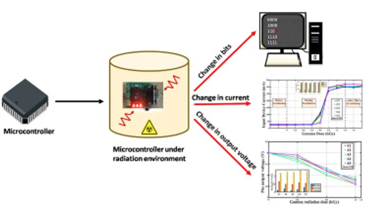
- TID Testing: This involves exposing components to a controlled dose of radiation, typically using gamma rays from a cobalt-60 source, to simulate years of cumulative exposure in a short time. Engineers measure parameters like current leakage and threshold voltage shifts to assess degradation. For example, a component might be tested to 100 krad (Si) to confirm it meets mission requirements.
- SEE Testing: Heavy-ion testing, often conducted at particle accelerators, simulates high-energy strikes to evaluate a component's susceptibility to single event effects. Metrics like the linear energy transfer (LET) threshold help determine the energy level at which SEE occur.
Testing must be mission-specific, accounting for the satellite’s orbit (e.g., low Earth orbit vs. geostationary orbit) and expected radiation environment. Data from these tests guide component selection and design adjustments, ensuring reliability in orbit.
5. Advanced Materials and Manufacturing for Radiation Hardening
Beyond component selection and design, the materials and manufacturing processes used in PCB fabrication play a role in radiation hardening. For instance, using substrates with low outgassing properties prevents material degradation under vacuum and radiation. Polyimide-based laminates, often used in space-grade PCBs, offer better thermal and radiation stability compared to standard FR-4 materials.
During manufacturing, strict quality control is essential to avoid defects that could exacerbate radiation damage. Processes like conformal coating can add an extra layer of protection against environmental factors, while thorough inspection ensures no weak points remain in the final assembly.
Balancing Cost and Performance in Radiation Hardening
While radiation hardening is critical, it often comes with trade-offs. Rad-hard components can be 10 to 100 times more expensive than commercial off-the-shelf (COTS) parts, and extensive shielding adds weight, increasing launch costs. Engineers must balance reliability with budget and mission requirements. For short-duration missions in low Earth orbit, where radiation levels are lower (typically less than 10 krad over 1-2 years), radiation-tolerant components—less robust than rad-hard but more affordable—may suffice. For deep-space missions, however, full radiation hardening is non-negotiable.
Future Trends in Radiation Hardening for Satellite PCBs
The field of radiation hardening is evolving rapidly. Advances in nanotechnology are leading to new materials, such as dendritic nanocomposites for capacitors, that offer exceptional radiation resistance (up to 20 Mrad in some cases). Additionally, machine learning is being used to predict radiation effects and optimize shielding designs, reducing the need for extensive physical testing. As satellite missions push further into deep space, these innovations will be crucial for ensuring reliability.
Conclusion: Building Reliable Satellite Payload PCBs
Designing satellite payload PCBs for the harsh radiation environment of space is a complex but achievable task. By leveraging radiation-resistant PCB components, addressing TID effects on PCBs through careful material selection, implementing SEE mitigation strategies at the design level, conducting rigorous radiation testing for space PCBs, and using effective shielding techniques for satellite electronics, engineers can ensure long-term reliability in orbit. At every stage—from component selection to final assembly—attention to detail is key. With the right approach, satellite systems can withstand the challenges of space, delivering consistent performance over missions that span years or even decades.
Whether you're working on a small CubeSat or a large geostationary satellite, integrating these radiation hardening techniques into your PCB design process will help safeguard your mission's success. Stay informed about emerging materials and testing methods to keep your designs at the forefront of space technology.


