ALLPCB


If you're looking to design a high-speed printed circuit board (PCB) using FR-4 material while ensuring signal integrity, you're in the right place. FR-4 is a popular and cost-effective PCB substrate, but it comes with challenges for high-speed applications due to its material properties. In this comprehensive guide, we'll explore FR-4 PCB high-speed design rules, techniques for maintaining signal integrity in FR-4 PCBs, methods for impedance control for FR-4 PCBs, tips on minimizing signal loss in FR-4 PCBs, and the key FR-4 PCB material properties for high-speed designs. Whether you're an engineer or a designer, this post will provide actionable insights to help you achieve reliable performance in your high-speed projects.
Why FR-4 for High-Speed PCB Design?
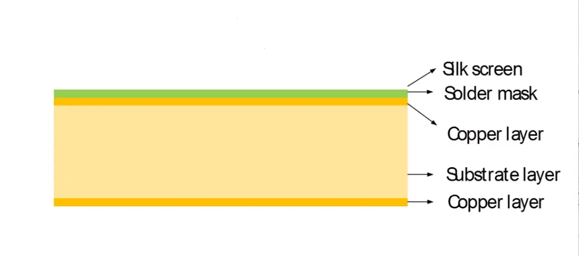
FR-4, a flame-retardant epoxy laminate, is the most widely used material for PCBs due to its affordability, mechanical strength, and decent electrical properties. However, when it comes to high-speed designs—where signals operate at frequencies above 100 MHz—FR-4's limitations, such as higher dielectric loss and less consistent dielectric constant, can impact performance. Despite these challenges, with the right design techniques, FR-4 can still be a viable choice for many high-speed applications, especially when cost is a critical factor.
In this blog, we'll dive into the strategies that make high-speed design on FR-4 not just possible, but successful. Let's start by understanding the material properties that play a role in these designs.
Understanding FR-4 PCB Material Properties for High-Speed Design
Before diving into design rules, it's essential to grasp the FR-4 PCB material properties for high-speed applications. These properties directly affect how signals propagate through the board and influence signal integrity.
- Dielectric Constant (Dk): FR-4 has a dielectric constant of approximately 4.2 to 4.5 at 1 MHz, though this value can vary with frequency and temperature. A higher Dk means slower signal propagation, which can be a concern for high-speed signals requiring precise timing.
- Loss Tangent (Df): FR-4's loss tangent, around 0.02 at 1 GHz, indicates higher dielectric loss compared to advanced materials like Rogers or PTFE. This loss contributes to signal attenuation, especially at frequencies above 1 GHz.
- Thermal Stability: FR-4 can handle moderate temperatures but may deform or degrade under extreme thermal stress, affecting reliability in high-speed systems with significant heat generation.
- Moisture Absorption: FR-4 absorbs moisture, which can alter its electrical properties and impact signal integrity over time.
While these properties pose challenges, careful design can mitigate their effects. Let's explore the specific techniques to ensure signal integrity in FR-4 PCBs.
Key FR-4 PCB High-Speed Design Rules
Designing high-speed circuits on FR-4 requires adherence to specific guidelines to overcome the material's limitations. Below are the most critical FR-4 PCB high-speed design rules to follow:
1. Control Trace Width and Spacing for Impedance Matching
Impedance mismatches can cause signal reflections, leading to data errors in high-speed designs. For FR-4, achieving the desired characteristic impedance (often 50 ohms for single-ended signals or 100 ohms for differential pairs) requires precise control of trace width and spacing.
- Use impedance calculators or simulation tools to determine trace dimensions based on FR-4's dielectric constant (around 4.3 at high frequencies).
- For a 50-ohm impedance on a standard 1.6mm FR-4 board with a ground plane, a trace width of approximately 6-8 mils (0.15-0.2 mm) is typical, though this varies with layer stackup.
- Maintain consistent spacing between differential pairs to avoid skew and ensure balanced signal propagation.
2. Minimize Trace Lengths to Reduce Delay and Loss
Long traces increase propagation delay and signal loss due to FR-4's higher loss tangent. To counter this:
- Keep critical high-speed traces as short as possible.
- Place high-speed components close together to reduce trace length.
- For signals above 1 GHz, signal loss can be significant (around 0.2 dB per inch at 5 GHz), so prioritize direct routing over complex paths.
3. Use Ground Planes for Signal Return Paths
A solid ground plane beneath high-speed traces provides a low-impedance return path, reducing electromagnetic interference (EMI) and crosstalk. With FR-4, ensure:
- No splits or cuts in the ground plane under high-speed traces, as this disrupts the return path and causes signal reflections.
- Stitch ground planes with vias if they exist on multiple layers to maintain continuity.
4. Avoid Sharp Corners in Trace Routing
Sharp 90-degree bends in traces can cause signal reflections due to impedance discontinuities. Instead:
- Use 45-degree angles or smooth curves for trace bends.
- For very high frequencies (above 5 GHz), even 45-degree bends may introduce small reflections, so consider mitered or rounded corners.
These rules form the foundation of high-speed design on FR-4. Next, let's focus on specific techniques for impedance control for FR-4 PCBs.
Impedance Control for FR-4 PCBs: Best Practices
Maintaining consistent impedance is critical for high-speed signals to prevent reflections and ensure reliable data transmission. Here are key strategies for impedance control for FR-4 PCBs:
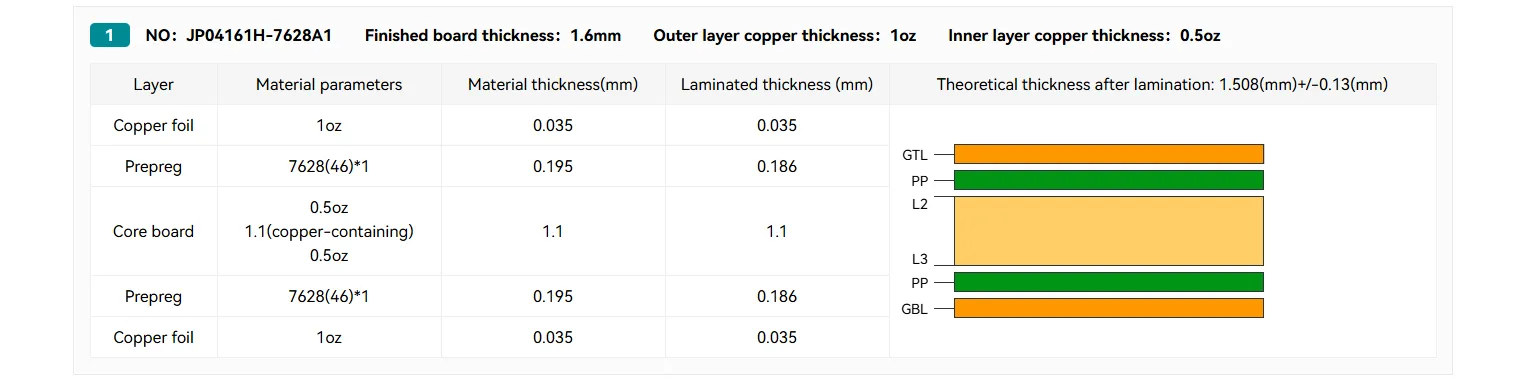
- Define Layer Stackup Early: Work with your PCB manufacturer to define a stackup that supports your impedance requirements. For example, a 4-layer FR-4 board might have signal layers on top and bottom with internal ground and power planes for reference.
- Account for Material Variations: FR-4's dielectric constant can vary by up to 10% between batches or manufacturers, affecting impedance. Specify a controlled dielectric constant when ordering materials, or design with a margin to accommodate variations.
- Use Differential Pair Routing: For high-speed interfaces like USB, PCIe, or HDMI, route differential pairs with matched lengths and consistent spacing to maintain impedance (typically 90-100 ohms for differential signals).
- Test and Simulate: Use simulation tools to model impedance before fabrication. Post-fabrication, use a Time Domain Reflectometer (TDR) to verify impedance on critical traces.
By focusing on these practices, you can achieve stable impedance even with FR-4's inherent variability.
Minimizing Signal Loss in FR-4 PCBs
Signal loss is a significant concern in high-speed designs on FR-4 due to its higher dielectric loss compared to premium materials. Here are actionable tips for minimizing signal loss in FR-4 PCBs:
- Choose Low-Loss FR-4 Variants: Some FR-4 materials are formulated for lower loss at high frequencies (loss tangent as low as 0.01 at 1 GHz). While more expensive than standard FR-4, they are still cheaper than alternatives like ceramic-filled laminates.
- Reduce Trace Length and Width: Thinner traces and shorter lengths reduce resistive and dielectric losses. However, balance this with impedance requirements to avoid mismatches.
- Optimize Via Design: Vias introduce parasitic capacitance and inductance, leading to signal loss. Minimize via count, use back-drilling for unused via stubs, and keep via transitions smooth.
- Control Surface Finish: Surface finishes like ENIG (Electroless Nickel Immersion Gold) provide better conductivity than HASL (Hot Air Solder Leveling), reducing resistive losses at high frequencies.
By implementing these strategies, you can significantly reduce signal attenuation and improve performance in your high-speed FR-4 designs.
Advanced Techniques for Signal Integrity in FR-4 PCBs
Ensuring signal integrity in FR-4 PCBs goes beyond basic design rules. Here are advanced techniques to tackle common issues like crosstalk, EMI, and timing skew:
1. Manage Crosstalk with Proper Spacing
Crosstalk occurs when adjacent traces interfere with each other, degrading signal quality. To minimize it:
- Maintain a spacing of at least 3 times the trace width between high-speed traces (3W rule) to reduce capacitive coupling.
- Route high-speed signals on different layers if spacing is constrained, ensuring a ground plane separates them.
2. Mitigate EMI with Shielding and Grounding
Electromagnetic interference can disrupt high-speed signals, especially in densely packed designs. Mitigate EMI by:
- Using ground planes and guard traces around sensitive high-speed lines.
- Adding decoupling capacitors near IC power pins to filter noise (e.g., 0.1 μF capacitors for frequencies up to 100 MHz).
3. Address Timing Skew in Differential Signals
For differential pairs, timing skew—where one signal arrives before the other—can cause data errors. Prevent this by:
- Matching trace lengths to within 5 mils (0.127 mm) for signals above 1 Gbps.
- Using serpentine routing to equalize lengths if direct paths differ.
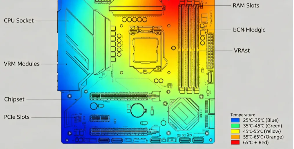
Thermal Management in High-Speed FR-4 Designs
High-speed circuits often generate heat, and FR-4's moderate thermal conductivity (around 0.3 W/m·K) can lead to hotspots. Poor thermal management impacts both performance and reliability. Consider these tips:
- Add thermal vias under high-power components to transfer heat to ground planes or heat sinks.
- Use thicker copper layers (e.g., 2 oz instead of 1 oz) for better heat dissipation, though this may affect impedance calculations.
- Ensure adequate airflow in the system design to prevent thermal buildup, as FR-4's glass transition temperature (Tg) is typically 130-140°C, beyond which it loses structural integrity.
Conclusion: Mastering High-Speed Design on FR-4 PCBs
Designing high-speed circuits on FR-4 PCBs is challenging but entirely achievable with the right techniques. By understanding FR-4 PCB material properties for high-speed applications and applying FR-4 PCB high-speed design rules, you can overcome the material's limitations. Focus on impedance control for FR-4 PCBs, work on minimizing signal loss in FR-4 PCBs, and use advanced methods to ensure signal integrity in FR-4 PCBs. These strategies will help you create reliable, cost-effective designs for applications ranging from consumer electronics to industrial systems.
With careful planning, precise routing, and attention to detail, FR-4 can support high-speed signals while keeping your project within budget. Start applying these techniques in your next design to achieve optimal performance and reliability.