 ALLPCB


Are you looking to build a DIY plant monitoring system with Arduino and a custom PCB? This guide will walk you through every step of creating an agriculture electronic project that monitors your plants’ health using sensors and a tailored circuit board. Whether you're a hobbyist or a small-scale farmer, this plant monitoring guide offers practical solutions to track soil moisture, temperature, and humidity, ensuring your plants thrive. Let’s dive into the details of designing custom PCB design sensors and assembling a powerful setup with Arduino.
Why Build a DIY Plant Monitoring System?
Growing plants, whether for a home garden or agricultural purposes, requires consistent care. Manually checking soil conditions or environmental factors can be time-consuming and prone to errors. A DIY plant monitoring Arduino system automates this process by collecting real-time data on key parameters like moisture, temperature, and light levels. With a custom PCB, you can create a compact, efficient, and personalized solution that integrates seamlessly with sensors and microcontrollers.
This project not only saves time but also helps optimize plant growth by providing precise data. Plus, designing your own PCB sensor Arduino setup gives you full control over the components and functionality, making it a rewarding agriculture electronic project.
What You’ll Need for Your Plant Monitoring System
Before starting, gather the necessary components and tools for this project. Here’s a comprehensive list to ensure you have everything ready for your DIY plant monitoring Arduino system:
- Arduino Board: A microcontroller like the Arduino Uno or Nano to process sensor data and control outputs.
- Sensors:
- Soil Moisture Sensor (Capacitive or Resistive) to measure water content in the soil.
- DHT11 or DHT22 Sensor for temperature and humidity readings.
- Light Sensor (LDR or Photodiode) to monitor light exposure.
- Custom PCB: Designed to connect sensors, the Arduino, and other components efficiently.
- Jumper Wires and Breadboard: For prototyping before PCB fabrication.
- Power Supply: A 5V USB power source or battery pack for the Arduino.
- Display (Optional): A small OLED or LCD screen to show real-time data.
- Software Tools: PCB design software for creating your custom board layout and Arduino IDE for coding.
Step 1: Planning Your Plant Monitoring System
The first step in this plant monitoring guide is to define what you want your system to do. For most setups, monitoring soil moisture, temperature, and humidity is essential. Decide if you want additional features like light monitoring or automated watering based on sensor readings.
Sketch a basic flowchart of how the system will work: sensors collect data, send it to the Arduino, which processes the information and outputs it to a display or triggers an action (like activating a water pump). This planning helps in designing the custom PCB layout and writing the code later.
Step 2: Designing the Custom PCB for Sensors
Creating a custom PCB design for sensors is a critical part of this agriculture electronic project. A PCB organizes the connections between the Arduino, sensors, and other components, reducing clutter and improving reliability compared to a breadboard setup.
Start by using a PCB design software to create a schematic. Place the Arduino as the central component. Connect the soil moisture sensor to an analog pin (e.g., A0), the DHT sensor to a digital pin (e.g., D2), and the light sensor to another analog pin (e.g., A1). Include power and ground traces to supply 5V to the sensors from the Arduino. If you’re adding a display or relay for automation, allocate pins and space for those as well.
For soil moisture sensors, ensure proper spacing for the sensor probes to avoid interference. Capacitive sensors, for instance, often have an impedance range of 100-500 ohms depending on soil wetness, so design the PCB to minimize noise in analog readings by keeping traces short and away from high-current paths.
Once the schematic is ready, convert it into a board layout, ensuring components are placed logically for easy assembly. Double-check for errors before sending the design for fabrication through a reliable service provider.
Step 3: Assembling the Hardware
With your custom PCB ready, it’s time to assemble the hardware for your PCB sensor Arduino setup. Follow these steps:
- Solder Components: Attach the Arduino, sensors, and other components to the PCB. Ensure proper orientation, especially for polarized components like capacitors or diodes.
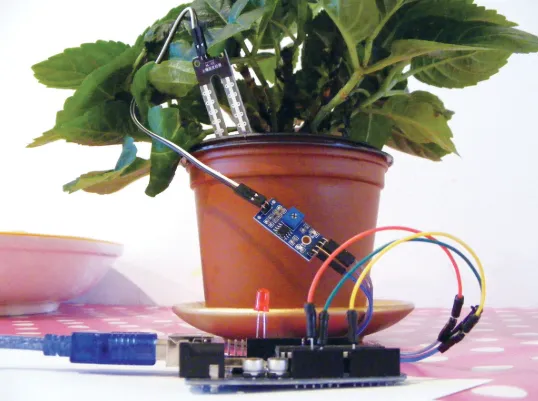
- Connect Sensors: If the sensors are not directly soldered, use headers or connectors to attach them to the PCB. For the soil moisture sensor, ensure the probes are clean and free from corrosion for accurate readings.
- Power Up: Connect the Arduino to a power source and verify that all components are receiving voltage (use a multimeter to check 5V at sensor pins).
- Test Connections: Before coding, test each sensor individually on a breadboard with sample Arduino code to confirm they work as expected.
Step 4: Coding the Arduino for Plant Monitoring
Now, let’s program the Arduino to read data from the sensors and display or act on it. Download the Arduino IDE and install necessary libraries like the DHT library for temperature and humidity sensors.
Here’s a basic code snippet to get started with reading sensor values:
#include

#define DHTPIN 2          // Digital pin connected to DHT sensor
#define DHTTYPE DHT11     // DHT sensor type (DHT11 or DHT22)
#define MOISTURE_PIN A0   // Analog pin for soil moisture sensor
#define LIGHT_PIN A1      // Analog pin for light sensor

DHT dht(DHTPIN, DHTTYPE);

void setup() {
  Serial.begin(9600);  // Start serial communication
  dht.begin();         // Initialize DHT sensor
}

void loop() {
  // Read temperature and humidity
  float humidity = dht.readHumidity();
  float temperature = dht.readTemperature();

  // Read soil moisture (value range depends on sensor, typically 0-1023)
  int moisture = analogRead(MOISTURE_PIN);

  // Read light level
  int light = analogRead(LIGHT_PIN);

  // Print values to Serial Monitor
  Serial.print("Humidity: ");
  Serial.print(humidity);
  Serial.print(" %\t");
  Serial.print("Temperature: ");
  Serial.print(temperature);
  Serial.print(" *C\t");
  Serial.print("Moisture: ");
  Serial.print(moisture);
  Serial.print("\t");
  Serial.print("Light: ");
  Serial.println(light);

  delay(2000);  // Wait 2 seconds before next reading
}
This code reads data every 2 seconds and outputs it to the Serial Monitor. You can modify it to display readings on an OLED screen or trigger a relay for watering when moisture levels drop below a threshold (e.g., a reading of 300 on a scale of 0-1023 for a typical resistive sensor).
Step 5: Testing and Calibration
Testing is crucial to ensure your DIY plant monitoring Arduino system works accurately. Place the soil moisture sensor in dry soil, then in wet soil, and note the readings. For a capacitive sensor, readings might range from 200 (dry) to 600 (wet) on a 0-1023 scale. Adjust thresholds in your code based on these values.
For the DHT sensor, compare its temperature and humidity readings with a known accurate device to ensure reliability. Light sensors may need calibration under different lighting conditions to set appropriate thresholds for plant needs.
Run the system for a few hours in a real garden or pot setup to identify any issues, such as sensor drift or wiring faults. Fine-tune the PCB layout or code if needed.
Step 6: Expanding Your System
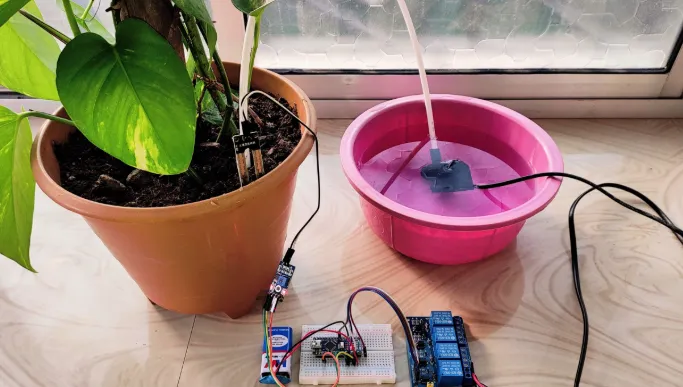
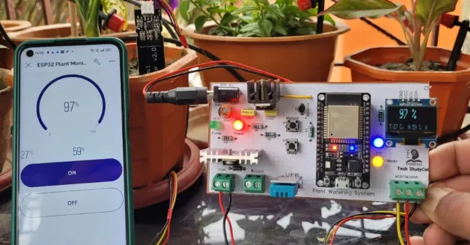
Once the basic setup is working, consider expanding your agriculture electronic project. Add a Wi-Fi module like the ESP8266 to send data to a smartphone app or cloud server for remote monitoring. You can also integrate a small water pump controlled by a relay to automate irrigation when soil moisture falls below a set level.
For larger setups, design a PCB with multiple sensor inputs to monitor several plants simultaneously. This scalability makes your system suitable for small farms or greenhouses.
Troubleshooting Common Issues
Even with careful planning, issues can arise in a PCB sensor Arduino project. Here are some common problems and solutions:
- Inaccurate Sensor Readings: Check for loose connections or interference in analog signals. Use shielded cables for long sensor wires and ensure the PCB traces are optimized to avoid noise.
- Power Issues: If the system resets or behaves erratically, verify the power supply provides stable 5V at sufficient current (typically 500mA or more for Arduino and sensors).
- Code Errors: If data isn’t displaying correctly, debug by printing intermediate values to the Serial Monitor to isolate the problem.
Benefits of Using a Custom PCB in Plant Monitoring
A custom PCB design for sensors offers several advantages over a breadboard or off-the-shelf breakout boards. It reduces wiring complexity, minimizes the risk of loose connections, and allows for a compact, professional-looking setup. Additionally, you can tailor the board to include only the features you need, optimizing cost and space.
For agriculture electronic projects, a custom PCB ensures durability in outdoor environments when paired with proper enclosures. This reliability is essential for consistent plant monitoring over long periods.
Conclusion
Building a DIY plant monitoring system using a custom PCB and Arduino is an exciting and practical project for anyone interested in gardening or small-scale farming. By following this plant monitoring guide, you can create a tailored solution to track soil moisture, temperature, humidity, and light levels with precision. From designing custom PCB design sensors to coding and testing, each step brings you closer to an automated, efficient way to care for your plants.
Start small with the basic setup described here, and as you gain confidence, expand your system with advanced features like remote monitoring or irrigation control. With the right tools and a bit of patience, your PCB sensor Arduino project can transform how you manage plant health, saving time and improving yields.
Take the first step today by gathering your components and designing your custom PCB. Your plants will thank you for the extra care!


