 ALLPCB


If you're new to electronics design and wondering what SMD active components are and how they fit into surface mount design, you're in the right place. SMD, or Surface Mount Device, active components are essential parts like transistors, diodes, and integrated circuits (ICs) that are mounted directly onto the surface of a printed circuit board (PCB). This guide will walk you through the basics of SMD active components, including SMD transistor identification, surface mount diode packages, IC package types, and soldering SMD components. We'll break down each topic with practical tips and detailed explanations to help you get started with confidence in your PCB projects.
What Are SMD Active Components?
SMD active components are electronic parts that can control or amplify electrical signals, unlike passive components like resistors or capacitors that only store or dissipate energy. These components are designed for surface mount technology (SMT), a method where parts are placed directly onto the PCB surface instead of being inserted through holes. This allows for smaller, lighter, and more efficient designs, which are crucial in modern electronics like smartphones, laptops, and IoT devices.
Active components include transistors, diodes, and ICs, each playing a unique role in a circuit. Their SMD versions come in compact packages that save space and support automated assembly. In the sections below, we'll dive into the specifics of these components and how to work with them.
Understanding SMD Transistor Identification
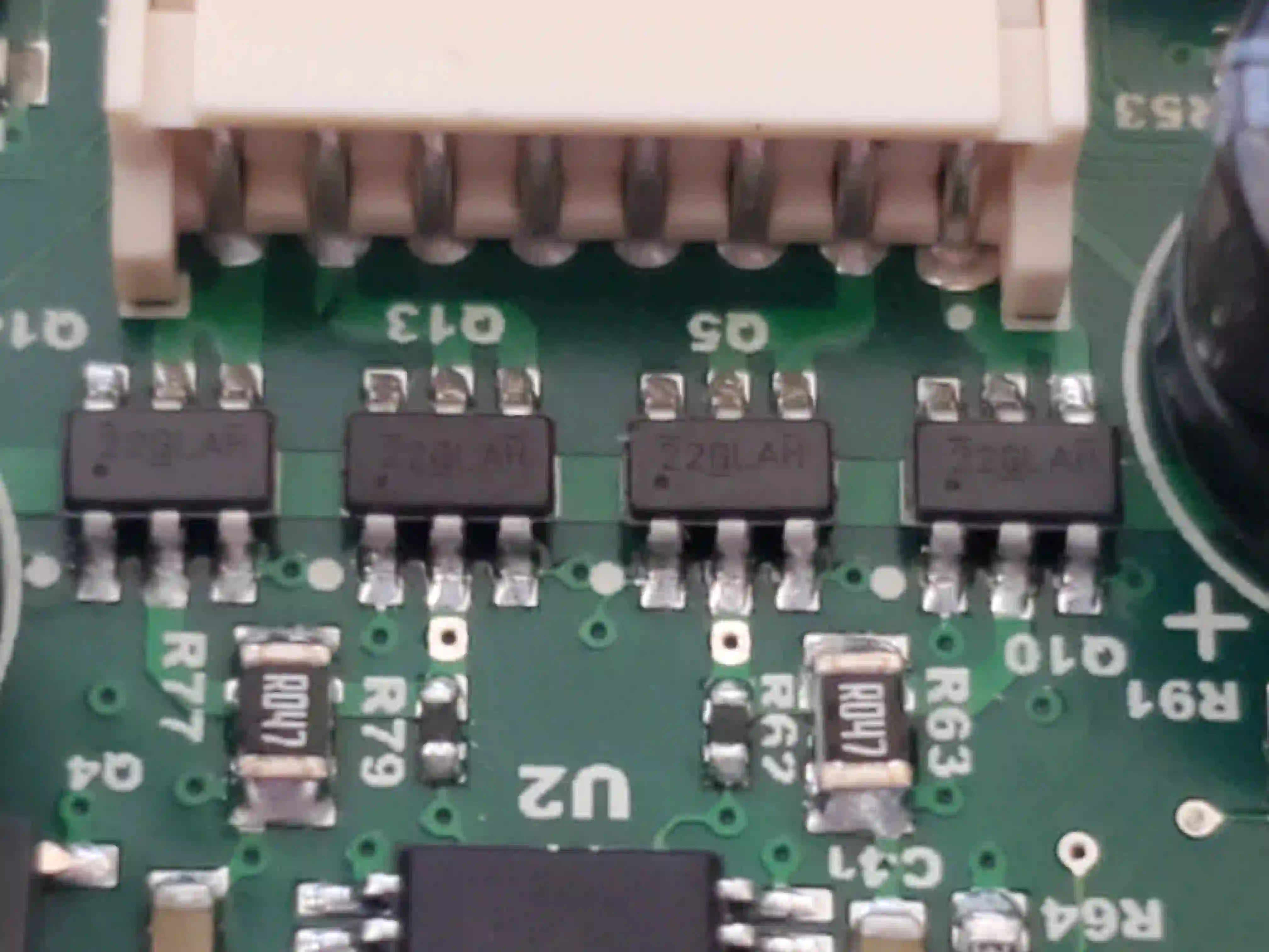
Transistors are fundamental active components used for switching or amplifying signals in a circuit. SMD transistors are tiny, often measuring just a few millimeters, and are identified by specific markings and package types. Learning SMD transistor identification is key to selecting the right component for your design and troubleshooting issues.
Most SMD transistors are marked with a code on their surface, usually a combination of letters and numbers. For example, a common NPN transistor might have a code like "1A" or "2N." These codes often correspond to the component's part number or characteristics, such as current rating or voltage capacity. To decode these markings, refer to the manufacturer's datasheet, which provides details like maximum collector current (often in the range of 100mA to 1A for small-signal transistors) or power dissipation (typically 200mW to 500mW for SMD types).
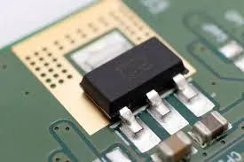
SMD transistors commonly come in packages like SOT-23, SOT-223, or TO-252. The SOT-23, for instance, is a small, three-pin package widely used for low-power applications. Knowing the package type helps in identifying the pin configuration—usually base, collector, and emitter for bipolar transistors. Always double-check the pinout in the datasheet, as incorrect connections can damage the component or the entire circuit.
Related Reading: Active Components in Signal Amplification: Design Techniques & Best Practices
Exploring Surface Mount Diode Packages
Diodes are another vital active component, used for directing current flow, protecting circuits, or converting AC to DC. When it comes to surface mount diode packages, their small size and variety can make selection tricky for beginners. Understanding the common packages and their applications can simplify your design process.
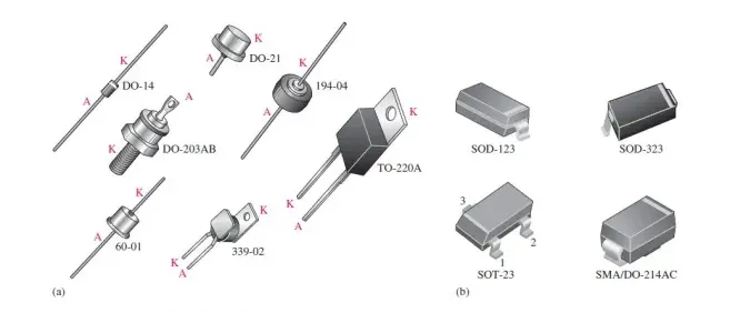
SMD diodes are available in packages like SOD-123, SOD-323, and SMA. The SOD-123 package, for example, is a small, two-lead design often used for general-purpose diodes with current ratings up to 1A and reverse voltage ratings around 100V. The SMA package, larger in size, can handle higher power levels, with current ratings up to 3A, making it suitable for power supply circuits.
Identification of SMD diodes often involves a marking code on the component, similar to transistors. For instance, a Schottky diode might be marked with "SS14," indicating its model and characteristics. Additionally, a line or band on one end of the diode typically marks the cathode, helping you orient it correctly on the PCB. Incorrect placement can lead to circuit failure, so always verify polarity before soldering.
A Closer Look at IC Package Types
Integrated Circuits (ICs) are the heart of most electronic devices, packing thousands or millions of transistors into a single chip. SMD ICs come in various IC package types, each designed for specific applications and space constraints. As a beginner, understanding these packages helps in selecting the right IC and designing an efficient PCB layout.
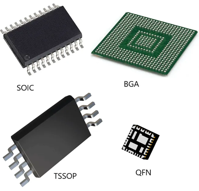
Common SMD IC package types include:
- SOIC (Small Outline Integrated Circuit): A rectangular package with pins on two sides, often with 8 to 16 pins. It's widely used for op-amps and microcontrollers, with pin spacing (pitch) of 1.27mm.
- QFP (Quad Flat Package): A square or rectangular package with pins on all four sides, ranging from 32 to over 100 pins. It's common in complex ICs like microprocessors, with a pitch as small as 0.4mm.
- BGA (Ball Grid Array): A package with solder balls on the underside instead of pins. It supports high pin counts (hundreds or thousands) and is used in advanced chips like CPUs, though it's challenging to solder manually due to its fine pitch (often 0.8mm or less).
- SOP (Small Outline Package): Similar to SOIC but often smaller, used for simpler ICs with fewer pins.
Each package type affects the PCB layout, soldering method, and heat dissipation. For instance, BGA packages require precise placement and often X-ray inspection to ensure proper soldering, as the connections are hidden underneath. When choosing an IC, consider the package size, pin count, and your assembly capabilities.
Related Reading: Component Packaging Options: Choosing the Right Package for Assembly
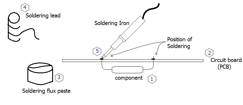
Mastering Soldering SMD Components
Once you've selected the right SMD active components, the next step is assembling them onto your PCB. Soldering SMD components can seem intimidating at first due to their small size, but with the right tools and techniques, it's a skill you can master. Proper soldering ensures reliable connections and prevents damage to sensitive components.
Tools You’ll Need
Before starting, gather these essential tools:
- A soldering iron with a fine tip (1mm or smaller) and adjustable temperature control.
- Solder wire, preferably with a diameter of 0.5mm to 0.8mm and a rosin core for better flow.
- Flux to clean and improve solder wetting on pads and leads.
- Tweezers for precise component placement.
- A magnifying glass or microscope for inspecting small parts and solder joints.
- Desoldering braid or a hot air rework station for corrections.
Step-by-Step Soldering Process
Follow these steps for soldering SMD components like transistors, diodes, and ICs:
- Prepare the PCB: Ensure the PCB is clean and free of dust or grease. Apply a thin layer of flux to the pads where the component will be placed to improve solder adhesion.
- Place the Component: Using tweezers, carefully position the component on the PCB pads, aligning the leads or pins correctly. For ICs, ensure all pins match the corresponding pads.
- Set the Soldering Iron Temperature: Set your soldering iron to a temperature suitable for the component, typically between 260°C and 300°C for most SMD parts. Too high a temperature (above 350°C) can damage components, while too low (below 250°C) may result in cold solder joints.
- Apply Solder: For components with multiple pins, like ICs, use the "drag soldering" technique. First, solder one pin to anchor the component. Then, apply solder to the tip of the iron and drag it across the remaining pins while feeding solder wire, ensuring each pin is connected to its pad. For two-lead components like diodes, solder one lead first, adjust placement if needed, then solder the other.
- Inspect the Joints: Check each solder joint under magnification. A good joint should be shiny and concave, fully covering the pad and lead. If you see dull or cracked joints, reheat and add more solder or flux.
- Clean Up: Remove excess flux residue with isopropyl alcohol and a brush to prevent corrosion over time.
Tips for Success
Practice on a scrap PCB or kit before working on your actual project. Avoid overheating components—limit soldering time to 2-3 seconds per joint. For heat-sensitive parts like ICs, consider using a hot air station for even heat distribution. If you make a mistake, use desoldering braid to remove excess solder without damaging the PCB pads.
Why Choose SMD Active Components for Your Design?
SMD active components offer several advantages over traditional through-hole components, making them the go-to choice for modern electronics design:
- Space Efficiency: Their compact size allows for denser PCB layouts, crucial for small devices. For example, an SMD IC in a QFP package can fit over 100 pins in a space smaller than 1 square inch.
- Improved Performance: Shorter lead lengths reduce parasitic inductance and capacitance, enhancing signal integrity at high frequencies (above 100MHz in many cases).
- Cost-Effective Assembly: SMD components are compatible with automated pick-and-place machines, reducing manufacturing time and labor costs.
- Lightweight Design: SMD parts contribute to lighter end products, which is essential for portable electronics.
However, they also come with challenges, such as the need for precise soldering skills and specialized tools. As a beginner, start with larger SMD packages (like SOIC or SOD-123) before moving to finer pitches like BGA.
Common Challenges and How to Overcome Them
Working with SMD active components can present hurdles, especially for those new to surface mount design. Here are some common issues and solutions:
- Component Misplacement: Small parts are easy to misalign. Use tweezers and magnification for accurate placement, and double-check orientation before soldering.
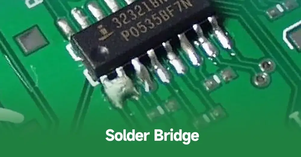
- Solder Bridges: Excess solder can create unwanted connections between pins, especially on fine-pitch ICs. Use a minimal amount of solder and clean up bridges with desoldering braid.
- Heat Damage: Overheating can destroy sensitive components. Stick to recommended temperatures and limit heat exposure time.
- Identification Errors: Mistaking one component for another due to similar markings is common. Always cross-reference markings with datasheets and store components in labeled containers.
Conclusion: Start Your Journey with SMD Active Components
SMD active components are the building blocks of modern electronics, enabling compact and powerful designs. By understanding SMD transistor identification, surface mount diode packages, IC package types, and soldering SMD components, you can confidently tackle surface mount design projects. Start small, practice your soldering skills, and always refer to datasheets for accurate information on components.
Whether you're designing a simple circuit or a complex device, mastering SMD technology opens up a world of possibilities. With the tips and techniques covered in this guide, you're well on your way to creating efficient, high-performance PCBs. Keep learning, experimenting, and refining your skills to stay ahead in the fast-evolving field of electronics design.


