Double-sided reflow soldering is a critical process in modern PCB assembly, allowing manufacturers to maximize space by placing components on both sides of a board. However, one of the biggest challenges in this technique is preventing component fallout during the second-pass soldering. This blog post dives deep into proven double-sided reflow soldering techniques, component fallout prevention strategies, solder paste selection for double-sided PCBs, and reflow profile optimization for double-sided assemblies. Whether you're an engineer or a manufacturer, you'll find actionable tips to ensure a reliable and efficient soldering process.
Understanding Double-Sided Reflow Soldering
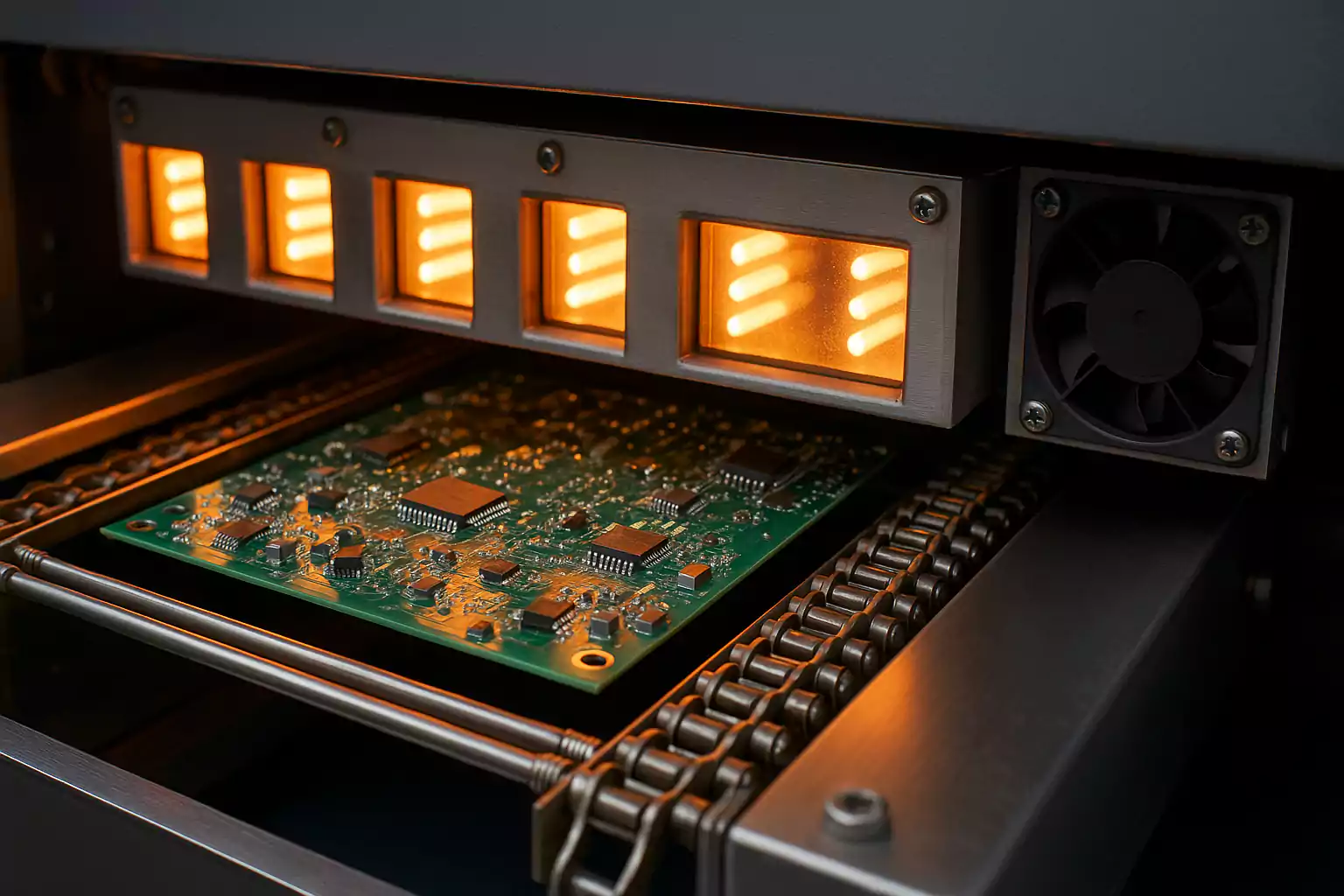
Double-sided reflow soldering involves assembling components on both the top and bottom sides of a printed circuit board (PCB) using a reflow oven. The process typically requires two passes through the oven: the first pass solders components on one side, and the second pass solders components on the opposite side. While this method is efficient for compact designs, the second pass can cause components on the first side to fall off due to gravity and remelting of solder joints.
The key to success lies in careful planning and execution. From selecting the right materials to optimizing the reflow profile, every step must be tailored to prevent issues like component fallout, cold solder joints, and thermal damage. Let's explore the essential techniques and strategies to master this art.
Key Challenges in Double-Sided Reflow Soldering
Before diving into solutions, it's important to understand the main hurdles in double-sided reflow soldering. The primary challenge is component fallout during the second pass. When the board is flipped, the solder on the first side remelts, and heavier components can detach due to gravity. Other issues include uneven heating, thermal stress on components, and potential misalignment during placement.
Statistics show that component fallout can lead to rework rates as high as 15-20% in poorly managed double-sided assemblies. This not only increases production costs but also delays timelines. Addressing these challenges requires a combination of material selection, process control, and equipment optimization.
Double-Sided Reflow Soldering Techniques
Mastering double-sided reflow soldering starts with adopting proven techniques. Below are some of the most effective methods to ensure a smooth process.
1. Use of Adhesives for Component Securing
One widely used technique is applying adhesives, often referred to as "red glue," to secure components on the first side before the second pass. This epoxy-based adhesive is dispensed under larger or heavier components to hold them in place during reflow. The adhesive cures during the first pass, providing extra stability when the board is flipped.
This method works best for components with high mass, such as large capacitors or connectors. However, it requires precise dispensing to avoid interfering with solder joints. Automated dispensing equipment can achieve accuracy within 0.1 mm, ensuring the adhesive is applied only where needed.
2. Staggered Component Placement
Another technique is to strategically place heavier components on the top side during the second pass. By soldering lighter components on the bottom side first, the risk of fallout during the second pass is minimized. This approach requires careful design planning but can significantly reduce issues without additional materials.
3. Two-Stage Reflow Process
A two-stage reflow process involves soldering the bottom side first with a lower-temperature profile to minimize thermal stress. During the second pass, a slightly higher temperature profile is used for the top side. This method reduces the likelihood of remelting solder on the first side excessively, keeping components in place.
Component Fallout Prevention Strategies
Preventing component fallout is the cornerstone of successful double-sided reflow soldering. Here are targeted strategies to address this issue.
1. Weight-Based Component Sequencing
As a rule of thumb, always solder the side with lighter components first. Components weighing less than 5 grams are less likely to fall off during the second pass, even if the solder partially remelts. For heavier components, consider using adhesives or alternative mounting techniques on the first side.
2. Minimize Solder Paste Volume on First Pass
Using a reduced amount of solder paste on the first side can limit the risk of excessive remelting during the second pass. A stencil thickness of 0.1 mm to 0.12 mm (instead of the standard 0.15 mm) can help control paste volume while still ensuring reliable joints.
3. Use High-Temperature Solder Alloys
Selecting a high-temperature solder alloy for the first pass can prevent remelting during the second pass. For instance, using a solder with a melting point of 217°C on the first side and a lower melting point alloy (around 183°C) on the second side creates a thermal barrier. This approach requires precise control of the reflow profile to avoid overheating components.
Solder Paste Selection for Double-Sided PCB
Choosing the right solder paste is critical for double-sided PCB assembly. The paste must provide strong adhesion, reliable wetting, and compatibility with the reflow process. Here are key factors to consider when selecting solder paste for double-sided applications.
1. Alloy Composition
Lead-free solder pastes, such as SAC305 (Sn96.5Ag3.0Cu0.5), are commonly used due to their compliance with environmental regulations. SAC305 has a melting point of approximately 217°C, making it suitable for most double-sided reflow processes. For high-reliability applications, consider SAC387 or SAC105 for better thermal fatigue resistance.
2. Flux Type and Activity
The flux in solder paste plays a vital role in cleaning surfaces and promoting wetting. For double-sided PCBs, select a no-clean flux with medium to high activity to handle potential oxidation during multiple reflow passes. This ensures strong solder joints without residue buildup that could affect reliability.
3. Particle Size and Viscosity
Solder paste with a Type 4 or Type 5 particle size (20-38 microns or 15-25 microns) is ideal for fine-pitch components often found on double-sided boards. Additionally, the paste should have a viscosity range of 800-1000 Kcps to ensure proper printing and adhesion during placement.
Reflow Profile Optimization for Double-Sided PCBs
A well-optimized reflow profile is essential to balance heat distribution, minimize thermal stress, and prevent component fallout. Here’s how to fine-tune the reflow profile for double-sided assemblies.
1. Preheat Stage Control
The preheat stage should ramp up at a rate of 1.5-2.5°C per second to avoid thermal shock. For double-sided boards, maintain a preheat temperature of 150-180°C for 60-90 seconds to ensure even heating across both sides. This reduces the risk of warping or uneven solder melting.
2. Soak Zone Adjustment
During the soak zone, maintain a temperature of 180-200°C for 30-60 seconds. This stage activates the flux and prepares the solder paste for reflow. For the second pass, slightly lower the soak time (by 10-15 seconds) to minimize heat exposure on the first side’s components.
3. Peak Temperature and Time Above Liquidus (TAL)
The peak temperature for SAC305 solder should be set between 235-245°C, with a Time Above Liquidus (TAL) of 30-60 seconds. For the second pass, reduce the peak temperature by 5-10°C to prevent excessive remelting of the first side’s solder joints. Automated thermal profiling tools can help monitor and adjust these parameters with precision.
4. Cooling Rate
A controlled cooling rate of 2-4°C per second is ideal to prevent thermal stress and solder joint cracking. Rapid cooling can cause defects, especially on double-sided boards with varying component densities. Use a reflow oven with adjustable cooling zones for best results.
Additional Tips for Success
Beyond the core techniques, a few extra practices can elevate the quality of your double-sided reflow soldering process.
- Board Support During Reflow: Use fixtures or carriers to support the PCB during the second pass. This prevents sagging or warping, especially for thinner boards (below 1.6 mm thickness).
- Regular Equipment Calibration: Ensure the reflow oven’s temperature sensors are calibrated regularly to maintain accuracy within ±2°C. Inconsistent heating can lead to cold joints or component damage.
- Post-Reflow Inspection: Use automated optical inspection (AOI) systems to check for misaligned components or defective solder joints after each pass. Early detection reduces rework costs.
Conclusion
Mastering the art of double-sided reflow soldering requires attention to detail, from selecting the right solder paste for double-sided PCBs to implementing component fallout prevention strategies. By adopting effective double-sided reflow soldering techniques and focusing on reflow profile optimization for double-sided assemblies, manufacturers can achieve high-quality results with minimal defects. The process may seem complex, but with the right approach, it becomes a reliable method for producing compact, high-performance electronics.
At ALLPCB, we’re committed to supporting engineers and manufacturers with advanced assembly solutions. By following the guidelines and strategies outlined in this post, you can tackle the challenges of double-sided reflow soldering with confidence and precision.
 ALLPCB


