ALLPCB


1. Overall framework
1.1 Tracking module
The Tracking module processes sensor information and computes the current frame pose in the active map in real time. It also decides whether to insert the current frame as a keyframe. In visual-inertial mode, the module estimates rigid-body velocity and IMU biases by adding inertial residuals into the optimization. When tracking is lost, the tracking thread attempts to relocalize the current frame in the Atlas. If relocalization succeeds, tracking is recovered and the active map is switched if necessary. If activation does not succeed after a period, that active map is stored as an inactive map and a new active map is reinitialized.
1.2 Local mapping module
The Local Mapping module adds keyframes and map points to the current active map, removes redundant frames, and optimizes the map using visual bundle adjustment or visual-inertial bundle adjustment over the neighboring keyframes of the current frame. In inertial mode, the mapping thread also uses maximum a posteriori (MAP) estimation to initialize and optimize IMU parameters.
1.3 Loop and map merging module
Whenever a new keyframe is added, this thread detects shared regions between the active map and the whole Atlas. If the shared region belongs to the active map, loop correction is performed; if it belongs to another map, the maps are merged into a single map and the merged map becomes the new active map. After loop correction, a separate thread runs global bundle adjustment to further optimize the map without affecting real-time performance.
1.4 Atlas module
The Atlas is a multi-submap system composed of a set of discrete maps. It maintains one active map used by the tracking thread to localize the current frame, while the local mapping thread continuously optimizes and updates that map with new keyframes. Other maps in the Atlas are inactive maps. The system builds a database of keyframe information based on a bag-of-words model for relocalization, loop detection, and map merging.
2. Pose estimation by fusing IMU and camera data
IMUs measure angular velocity and linear acceleration but exhibit significant drift, making double integration of IMU data alone unreliable for long-term pose estimation. However, IMUs provide good short-term estimates during fast motions, which is a weakness for cameras because high-speed motion causes motion blur or insufficient overlap between frames for feature matching. With an IMU, acceptable pose estimates can be maintained during intervals when camera data are unreliable, which pure vision SLAM cannot achieve. Conversely, camera data have negligible drift, so images can correct IMU drift and keep pose estimates accurate after slow motion. When images change, it is intrinsically ambiguous whether the change is due to camera motion or scene variation, so pure visual SLAM struggles with dynamic obstacles. The IMU senses the platform motion directly and therefore partially mitigates the impact of dynamic objects. The main steps are as follows:
- Acquire images from the camera and inertial measurements from the IMU. The IMU sampling rate is higher than the camera rate.
- Extract feature points from each camera frame, compute descriptors for those features (ORB descriptors are used in ORB-SLAM), and match features. Optical-flow tracking may also be used as an alternative.
- Preintegrate multiple IMU measurements to compute the relative position and velocity between the two frames corresponding to those IMU measurements.
- IMU initialization (the method used by ORB-SLAM3). The goal is to obtain good initial values for IMU parameters: velocity, gravity, and biases.
- Vision-only: Use the classic ORB-SLAM visual-only initialization. Run continuously at a keyframe rate of 4 Hz for 2 s to obtain a scaled map that typically includes around 10 keyframes and hundreds of map points, then refine with visual-only bundle adjustment.
- Inertial-only: Estimate optimal IMU parameters using the stabilized data from the monocular visual SLAM initialization plus the IMU measurements between those keyframes. The parameters include the scale factor, gravity direction, IMU sensor biases, and unscaled velocities of keyframes. These IMU measurements form a state vector used in an optimization problem. Once inertial optimization completes, frame poses, velocities, and 3D map points are scaled by the estimated scale and rotated so the z axis aligns with the estimated gravity direction.
- Visual-inertial: After reasonable visual and inertial estimates are available, perform a joint optimization to refine these parameters further.
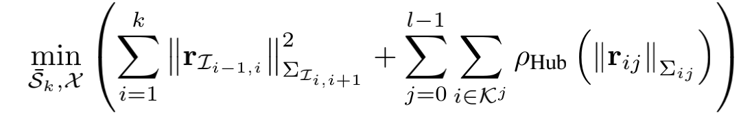
Combining the inertial residuals and visual residuals, visual-inertial SLAM is formulated as a keyframe-based minimization problem. The backend minimizes the combined cost function.
During tracking, only the poses of the last two frames are optimized while keeping map points fixed. For mapping, solving the full-map optimization becomes difficult when the map grows large. ORB-SLAM3 uses a sliding-window approach that treats a window of keyframes and their map points as the optimization variables.
3. Strengths, weaknesses, and improvement opportunities of the feature-based tracking module
ORB-SLAM3's visual frontend extracts feature points and matches descriptors. Having descriptors simplifies map maintenance tasks such as relocalization, loop closure, and global optimization. In indoor environments with abundant visual covisibility, this approach improves localization accuracy and local stability. However, it has drawbacks: computing descriptors for extracted feature points in every frame is time-consuming. During tracking, fast motion causing motion blur can easily lead to tracking loss. Pure visual ORB-SLAM3 heavily depends on successful feature extraction and matching; in textureless environments it cannot obtain enough stable matches, and bundle adjustment lacks sufficient input to correct pose drift. To address this, alternative approaches exist, notably combining feature extraction with optical-flow tracking. That approach is more robust for tracking but makes global map construction harder and still requires separate feature extraction/descriptors for loop closure and relocalization. Visual-inertial ORB-SLAM3 mitigates the heavy dependence on features by using IMU constraints to correct drift and recover scale, partially solving the problem of feature scarcity.
ORB-SLAM3 introduces the Atlas system: if tracking is lost, the current frame can query the Atlas DBoW database. The query uses all available priors to find similar keyframes across all maps. Once candidate keyframes are found, the corresponding map and matched map points can be used for relocalization, which significantly improves performance and robustness.
One notable change in this ORB-SLAM3 update is the introduction of the Atlas map, which opens a new direction for research. Since this is an initial version, there is considerable room for improvement on this front. IMUs and cameras are complementary; researching better ways to fuse them for improved performance is another promising direction. IMU initialization also has limitations, so developing improved IMU initialization methods is a possible area for enhancement.