ALLPCB


Overview
Protecting edge 5G private networks and applications faces many challenges. Complex attacks based on AI and ML require real-time responses.
Paituo Networks' security platform has integrated ML and AI capabilities to deliver autonomous real-time ML and AI-driven event response.
The NVIDIA team and Paituo Networks collaborated on an intelligent traffic offload (ITO) design with a clear goal: enable enterprises to adopt 5G while maintaining security, performance, and efficiency. The ITO is positioned as a foundational solution to help modern enterprises build fast, secure 5G private network infrastructure.
DPU Role and Performance
Data processing units (DPU) are key components for edge computing AI and ML infrastructure, hyperscale telecommunications clouds, and any cloud that provides IT, OT, or IoT networks and services. Enterprise customers can use ITO to extend security functionality and increase total firewall throughput by at least 5x.
ITO Enhancements
Several enhancements have been introduced to ITO to offer more deployment options, easier installation, and higher performance. These include:
- Added support for NVIDIA BlueField-3 DPU
- Expanded deployment mode with L3 routing capability
- NAT-based offload
Static and dynamic routing provide additional deployment choices, while NAT-based offload helps secure the internet edge, protecting end-user identities while offloading traffic.
ITO Available on NVIDIA BlueField-3
In addition to integration with NVIDIA BlueField-2 DPU, the product range now includes support for NVIDIA BlueField-3 DPU.
The ITO solution accelerates Paituo Networks' VM series next-generation virtual firewalls (NGFW) via NVIDIA BlueField DPUs, substantially increasing throughput while reducing infrastructure cost.
ITO Enhanced Option: L3 Support
Initial ITO deployments supported a vWire firewall insertion mode. In vWire mode, the firewall does not perform any switching or routing and simply acts as an in-line block. This is useful in environments that do not require routing or switching, or where the firewall receives all traffic from a single L3 domain.
The new L3 mode expands the ability to use security solutions within data centers by allowing the firewall to switch and route traffic across network domains.
Figure 1 illustrates packet flow in L3 mode.
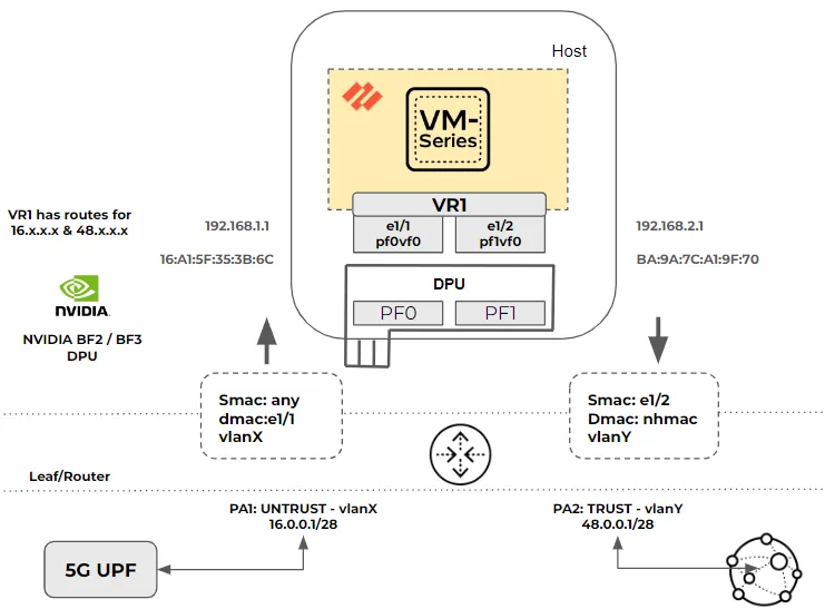
Packet Flow Characteristics
- Interfaces e1/1 and e1/2 are configured in L3 mode.
- VR1 is configured with static or dynamic routes to the 5G L3 router or UPF and to the internet peer router.
- Tagged and untagged traffic are supported. Routers and DPUs or NICs support access or trunk mode.
The L3 mode packet flow is as follows:
- Packets are sent from the 5G UPF (L3 router) to the L3 leaf/router.
- When packets arrive at router port PA1, which connects to the DPU and SmartNIC PF0, the port is programmed to add VLAN X tagging to the packets.
- Packets arrive at DPU port pf0vf0 and are forwarded to the VM series firewall, regardless of VLAN removal.
- The firewall operates in L3 mode. It determines the packet's next hop and corresponding MAC address.
- The firewall updates the DPU and SmartNIC via gRPC with the new destination MAC address and vlanY if required.
- Tagged packets with vlanY are sent from DPU and SmartNIC port PF1 to router port PA2.
- If packets are untagged, router port PA2 can add vlanY tagging.
- Packets are forwarded to the next-hop address and delivered to the internet peer device. With dynamic routing, any routing changes cause the VM series firewall to update the DPU with the new next-hop MAC address.
ITO Enhanced Option: NAT Support for vWire and L3
In many 5G deployments and certain hyperscale enterprise environments, the PAN VM series virtual NGFW secures the internet edge or north-south traffic. In such deployments, NAT mode can be used to ensure end-user devices are not directly exposed to the internet.
NAT support with ITO is available in both vWire and L3 deployment modes. Multiple NAT modes can be configured over IPv4, including source NAT with dynamic IP and port translation, destination NAT with port translation, and port forwarding.
Figure 2 shows the packet flow for configured NAT policies.
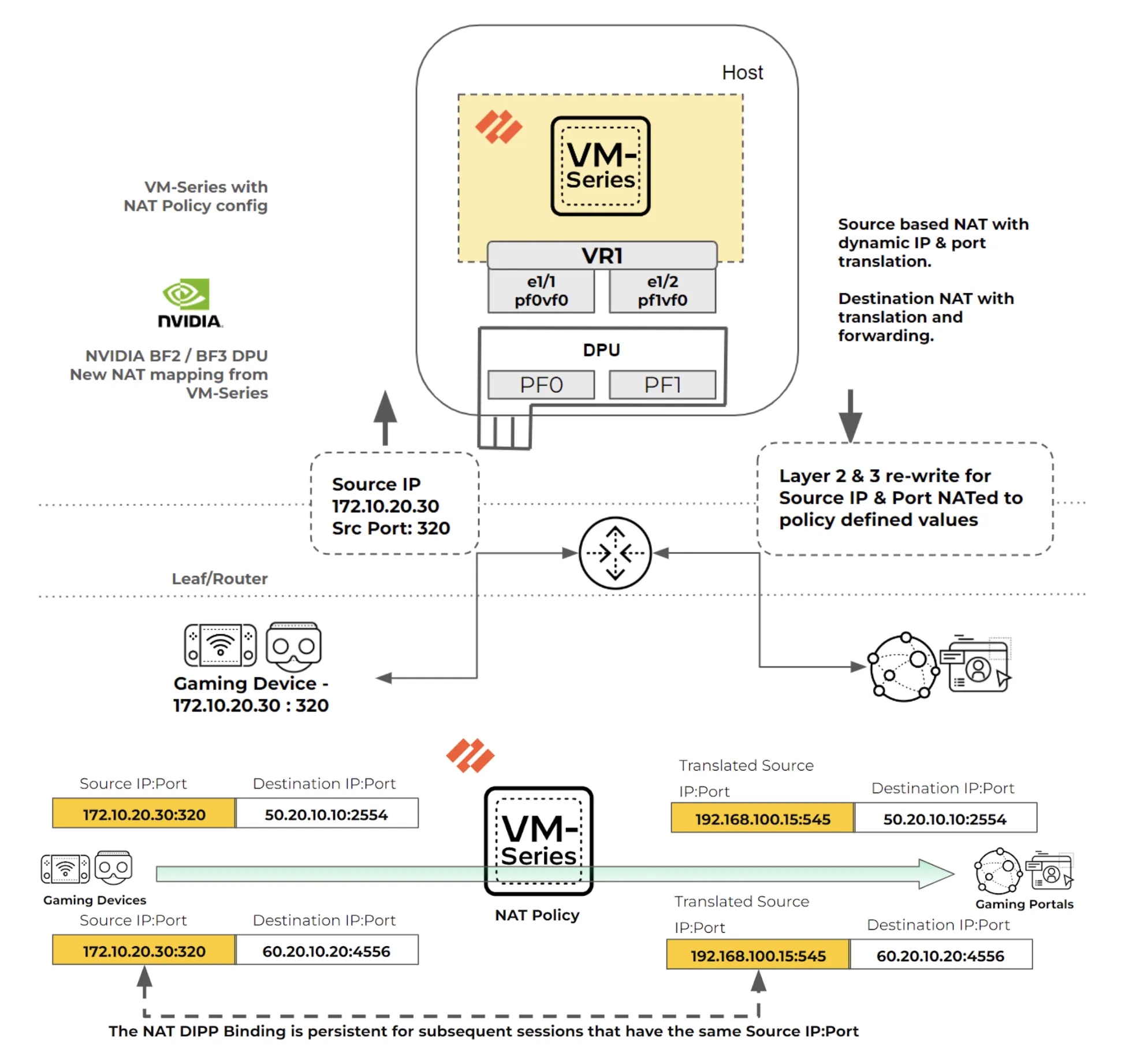
NAT Policy Configuration and Packet Flow
- The VM series firewall is configured with NAT policies to perform source NAT mapping from private IP and port to dynamic public IP and port.
- Defined NAT policies can also perform destination IP and port translation and forwarding.
Example packet flow when NAT is applied:
- A packet from a 5G device is sent through the 5G UPF or L3 router with source IP and port 172.10.20.30:320.
- The packet reaches the VM series firewall, where a source NAT policy maps 172.10.20.30:320 to 192.168.100.15:545.
- The VM series firewall rewrites L2 and L3 headers according to the NAT policy, which may be source NAT with dynamic IP and port translation or destination NAT with port translation and forwarding.
- After NAT translation, the VM series firewall updates the DPU and SmartNIC via gRPC.
- SNAT DIPP maintains persistence by binding the private source IP and port pair to a specific public (translated) IP and port pair for subsequent sessions from the same original source tuple. In this example, 172.10.20.30:320 and its translated 192.168.100.15:545 remain persistent for multiple destination IP and port pairs.
Conclusion
With the enhanced ITO features, deployments of the VM series NGFW can now be extended in both vWire and L3 modes. NAT functionality continues to be supported on VM series firewalls with ITO. These features are also available on NVIDIA BlueField-3 DPU, enabling higher throughput and improving security performance by at least 5x.