 ALLPCB


Overview
With advances in technology, PLCs are increasingly used in industrial control. The reliability of PLC control systems directly affects the safety and economic operation of industrial facilities. A system's immunity to interference is a key factor for reliable operation. PLCs are installed both in control rooms and in the field on equipment such as motors, often located in harsh electromagnetic environments created by high-power circuits and equipment. Improving PLC reliability requires understanding the various interference sources in advance.
EMI Types and Their Impact on Systems
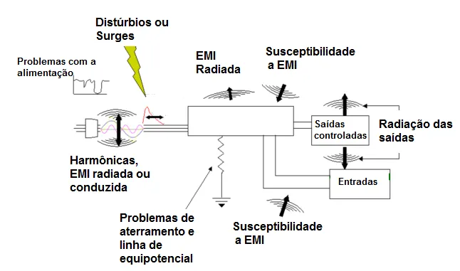
Interference affecting PLC control systems originates from the same sources that affect industrial control equipment in general. These sources are usually located where current or voltage changes rapidly; such regions of violent charge movement are the noise sources.
Interference can be classified by cause, by coupling mode, and by waveform characteristics. By cause: discharge noise, surge noise, high-frequency oscillation noise, etc. By waveform: continuous noise, intermittent noise, etc. By coupling mode: common-mode and differential-mode interference. Common-mode interference is the potential difference of a signal relative to ground, mainly caused by coupling from the power network, ground potential differences, and electromagnetic radiation inducing voltages on signal lines. Common-mode voltages can be large; for systems with poor isolation the common-mode voltage on transmitter outputs can exceed 130 V. Common-mode voltage can convert to differential-mode voltage through asymmetric circuits, directly affecting measurement and control signals and causing component damage. Differential-mode interference refers to unwanted voltage between the two signal conductors, mainly caused by electromagnetic coupling between signals or by conversion from unbalanced circuits. Differential-mode noise superimposes directly on the signal and degrades measurement and control accuracy.
Main Sources of Electromagnetic Interference in PLC Systems
1) Radiated interference from the surrounding environment
Radiated electromagnetic fields are produced by the power network, transient events in electrical equipment, lightning, radio and TV broadcasts, radar, high-frequency induction heating, and other sources; these are collectively called radiated interference and have complex spatial distributions. If a PLC system is placed in a radiated RF field, it can pick up interference via two main paths: direct radiation coupling into the PLC circuitry, or radiation coupling into communication networks and being introduced through communication lines. Radiated interference depends on equipment layout and the magnitude and frequency of local electromagnetic fields. Typical protections include shielded cables, local shielding of PLC enclosures, and high-voltage discharge components.
2) Conducted interference from external wiring
Interference introduced via power and signal lines is known as conducted interference. This type of interference can be severe at industrial sites in China.
3) Interference from the power supply
Many PLC system faults are caused by interference coupled through the power supply. Power for PLC systems is usually derived from the mains. Because the power grid covers a wide area, it is susceptible to many sources of electromagnetic disturbance that can induce voltages on supply lines. Transients inside the grid, such as switching surges, startup and shutdown of large equipment, harmonics from rotating machinery, and short-circuit transients, propagate along transmission lines to the power input. PLC power supplies are often isolated, but practical isolation is limited by device construction and distributed parasitic elements such as capacitance. Absolute isolation is impossible in practice.
4) Interference introduced via signal lines
Various signal transmission lines connected to the PLC not only carry desired signals but also pick up external interference. There are two main coupling paths: one is grid interference injected through the transmitters or shared power supplies of signal instruments, which is often overlooked; the other is external induction on the signal lines from the ambient electromagnetic field. Interference on signal lines can cause I/O anomalies and large measurement errors, and in severe cases can damage components. In systems with poor isolation, signals can interfere with each other, producing ground return currents that cause logic data corruption, false operations, or system lockups. Damage to I/O modules caused by signal-induced interference is a common cause of PLC system faults.
5) Interference due to grounding system issues
Grounding is an effective measure to improve electromagnetic compatibility (EMC). Correct grounding suppresses incoming interference and reduces emissions from equipment. Incorrect grounding can introduce severe interference that prevents PLC systems from functioning normally. PLC grounding typically includes system ground, shield ground, AC ground, and protective earth. A poorly organized grounding system can create unequal ground potentials and ground loops, generating currents that disrupt system operation. For example, cable shields must be grounded at a single point; if both ends are grounded there can be a potential difference and shield current will flow. Under abnormal conditions such as lightning, ground currents can become very large.
Additionally, shield layers, grounding conductors, and earth can form closed loops that experience induced currents in varying magnetic fields; those induced currents can couple into signal conductors and disturb circuits. If system ground is mixed with other grounds, ground loop currents can produce unequal potentials on ground conductors, affecting PLC logic and analog circuits. PLC logic voltages have low noise tolerance, so ground potential variations can disrupt logical operations, corrupt data, or cause crashes. Analog ground potential differences reduce measurement accuracy and lead to signal distortion and false actions.
6) Interference originating inside the PLC system
Internal interference stems from electromagnetic radiation among internal components and circuits, such as logic circuits radiating into analog circuits, interactions between analog ground and logic ground, and component mismatches. These issues are part of the PLC manufacturer's EMC design and are generally beyond the application-side scope. It is advisable to select systems with proven application performance.
Common Interference Symptoms
- Motors rotate irregularly when the system issues a command.
- Digital displays jump when the signal is zero.
- Sensor signals acquired by the PLC do not match the actual measured parameters; errors are random and unpredictable.
- Shared power supplies with AC servo systems or displays cause abnormal operation.
Practical Measures to Reduce PLC System Interference
1) Ideally, select devices with good isolation, use quality power supplies, route power and signal cables properly, and implement reasonable power grounding. These measures often require cooperation among multiple equipment suppliers and can be expensive and difficult to implement fully.
2) Use analog signal isolators, also called signal transmitters or signal conditioners. Their primary function is to provide interference immunity. Because they offer strong isolation, signal isolators are widely used in automation systems. For complex industrial sites and increasingly complex control programs, isolators provide three-terminal isolation (input, output, and power) for analog signals, and are an effective anti-interference measure in modern automation.
Why Choose Signal Isolators?
- They are simple to use, reliable, and relatively low cost, and can address multiple interference types simultaneously.
- They reduce the workload for designers and system integrators; even complex systems can achieve high stability and reliability with proper isolation.
Signal Isolator Working Principle
A typical isolator first conditions the PLC input signal using semiconductor modulation. The conditioned signal is then converted across the isolation barrier using optoelectronic or magnetic coupling, demodulated back to the original or a different signal on the output side, and the output power supply is also isolated. This ensures that the transformed signal, its power, and ground are electrically independent.
How to Choose an Isolator
An isolator sits between two system channels, so first determine the required input and output functions and ensure the isolator's input/output modes (voltage, current, loop-powered, etc.) match the connected interfaces. Important parameters include accuracy, power consumption, noise, insulation strength, and any bus communication features. Noise affects accuracy, and power dissipation affects reliability; these factors require careful selection. In summary, suitability, reliability, and product cost-effectiveness are the main principles when choosing an isolator.
Eleven Practical Methods to Solve Analog Signal Interference
- Install a 1:1 signal isolator.
- Add ferrite choke rings.
- Use an isolation transformer for PLC power.
- Route discrete (digital) I/O and analog signals on separate cables.
- Use individually shielded cable for analog signals; prefer 4-20 mA signal standards.
- For analog signal loads that drive solenoid valves, use at least 1.5 mm2 cable where possible.
- Do not use the same multicore cable for analog and digital signals, and do not share cables with power lines.
- Use shielded cable for PLC I/O lines; leave the shield unterminated at the far end and tie it to ground at the PLC end.
- Keep signal cables away from strong interference sources such as variable frequency drives, high-power rectifiers, and large motors.
- Do not combine analog and digital signals in the same multicore cable, and do not share the cable with power lines.
- To reduce electronic interference on analog signals, use twisted-pair shielded cable. Ideally the shield should be grounded at both ends, but if a potential difference exists between cable ends it will create shield currents that interfere with the analog signal; in such cases, ground the shield at only one end.


