 ALLPCB


Overview
As is well known, the three main methods for addressing EMC are shielding, grounding, and filtering. This article focuses on shielding and its role in EMC control.
Part 1
Shielding Principles
First, define shielding. Shielding uses metal to separate two spatial regions to control the influence of the electric field, magnetic field, and electromagnetic waves from one region on the other, typically addressing both induction and radiation mechanisms.
Shielding is commonly applied in two ways: shielding the source of interference to prevent electromagnetic fields from radiating outward and affecting other sensitive equipment, and shielding sensitive equipment to prevent it from being affected by external electromagnetic fields.
Shielding is effective for several reasons:
- Eddy current loss: the shield can absorb energy from external or internal electromagnetic waves coming from wiring, cables, components, circuits, or systems.
- Reflection of energy: electromagnetic waves reflect at the interface of the shield, which is why shields are widely used in many products. This can be explained by impedance mismatch in transmission line theory.
- Skin effect: at high frequencies, thin and thick shields provide similar attenuation due to skin effect.
- Cancellation: electromagnetic induction in the shield can generate opposing fields on the shield surface, which partially cancel the interfering fields.
Part 2
Basic Principles of Shielding Design
Below are common measures and practices used in shielding design.
- Keep shield structures as simple as possible. Minimize unnecessary holes and avoid adding extra seams.
- Avoid long narrow slots. For ventilation use circular holes arranged in arrays. When shielding conflicts with thermal dissipation, prefer many small holes rather than a few large ones.
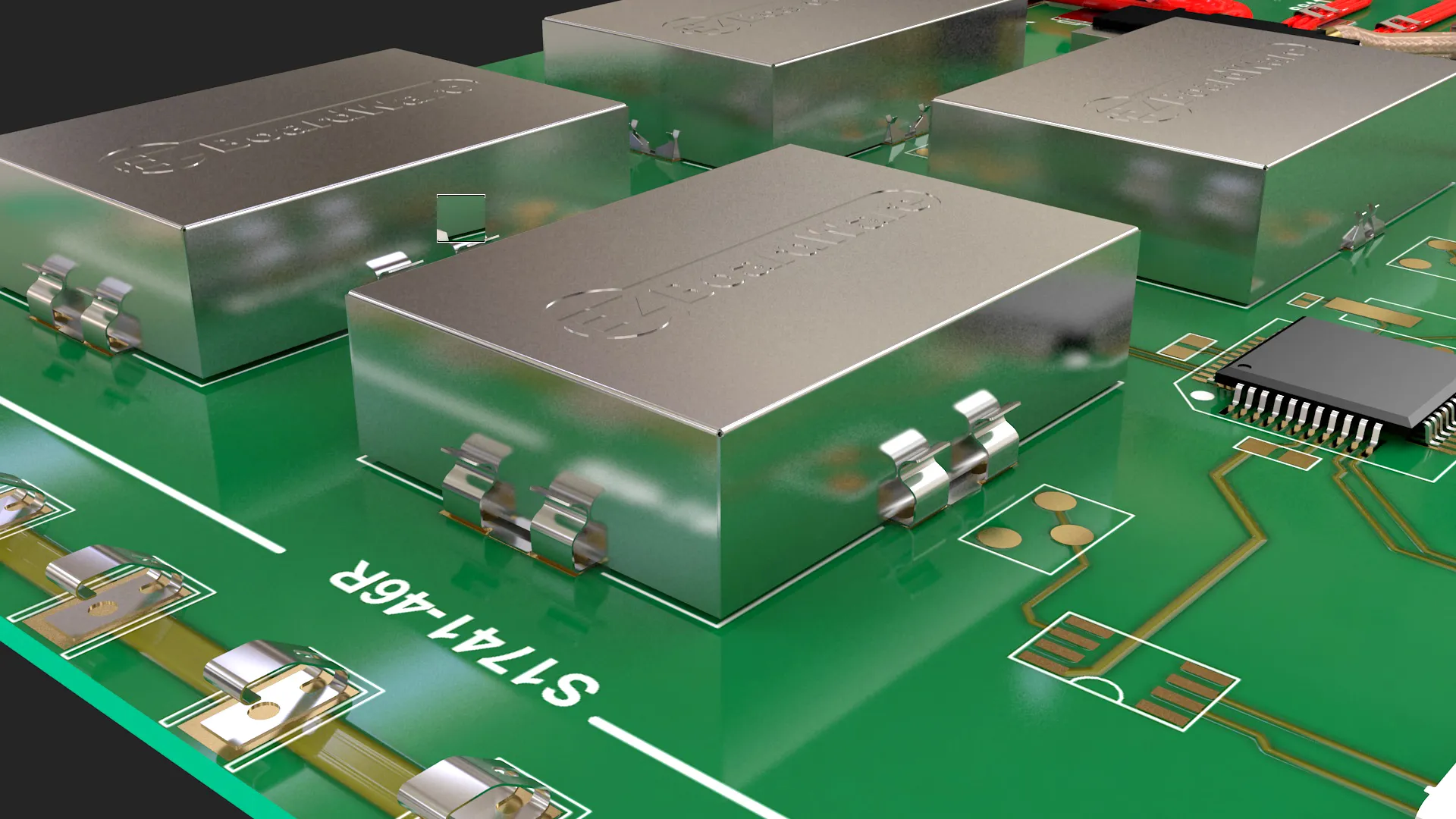
- Pay attention to cable handling. Do not route shielded cable straight through an enclosure without bonding; the cable shield must be 360° bonded to the enclosure. Cable treatment is often more important than the shield itself.
- Electrical continuity of the shield structure is the most important factor affecting shielding performance; the intrinsic shielding properties of the material are relatively less significant, except for low-frequency magnetic fields.
- Shielding effectiveness is determined by the maximum dimension of apertures rather than the total open area. Design circular holes when possible, then square holes, and avoid long slots.
- The maximum size of apertures or slots should be smaller than the smaller of the following two limits: (1) one one-hundredth of the wavelength corresponding to the highest operating frequency, and (2) 0.15 m when the shield carries common-mode current.
- At frequencies of interest, use shielded cables with low transfer impedance; prefer cables with double, triple, or quad braid shielding.
- Avoid floating metal parts. Floating metal can develop a high common-mode voltage relative to a noise source and radiate strongly. Large metal areas have higher distributed capacitance and are prone to electric field coupling. Bond such parts to local ground. Heatsinks, metal shields, metal brackets, and unused metal areas on PCBs should be grounded.
- For connectors carrying signals, use connectors with shielded shells, especially for high-frequency signals.
- Place ventilation or observation openings where radiated fields are lower. If windows are made of rectangular slots, consider the polarization of the radiation at the window location and avoid orienting the long side of the rectangle along the direction of strongest polarization to minimize radiated energy.
- Shielded cable shields should be grounded at both ends unless the connected equipment is immune and does not generate EMI, for example passive sensors. The cable shield should be connected to the metal chassis of the connected equipment; if the connected product has a plastic enclosure, connect the shield to the PCB ground of the connected product.
Part 3
Shielding Materials and Joints
Shielding design is closely related to how joints are made between metal surfaces. A joint uses conductive materials to connect two metal surfaces, forming a low-impedance electrical connection.
Where two metal parts meet, sealing gaskets are usually used at the joints. Common gasket types include metal mesh strips, conductive elastomers, spiral-wound conductive tubing, multilayer conductive elastomers, finger stock, and conductive fabric gaskets.
Points to note when using shielding materials:
- Ensure good electrical contact at mating surfaces by removing coatings and paint at contact areas, and provide adequate compression determined by the fastening force. Excessive compression can damage the gasket, reduce elasticity, and impair sealing.
- Keep contact surfaces clean and protect gaskets from corrosion, since corrosion reduces contact conductivity and shielding effectiveness.
- Shielding materials have finite service life and must meet the product's lifetime and applicable environmental regulations.
- Prefer mounting methods that ensure direct contact, such as snap-in features or mounting grooves. Adhesive-backed PSA tape should be a secondary choice.
- As a guideline, contact resistance between mating joints should be less than 2 mΩ, and the resistance between any two points in the expected equipotential bonding system should be less than 25 mΩ. When these conditions are met, the system can be considered well bonded from an EMC perspective.


