 ALLPCB


01 Basic concepts
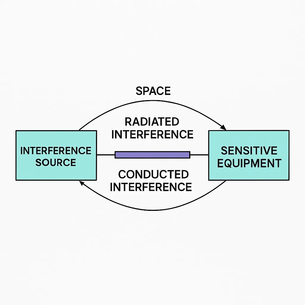
Electromagnetic noise propagates or couples and is commonly classified into two categories: conducted noise and radiated noise. Electromagnetic noise that travels via conductors is called conducted noise; noise that travels through space is called radiated noise.
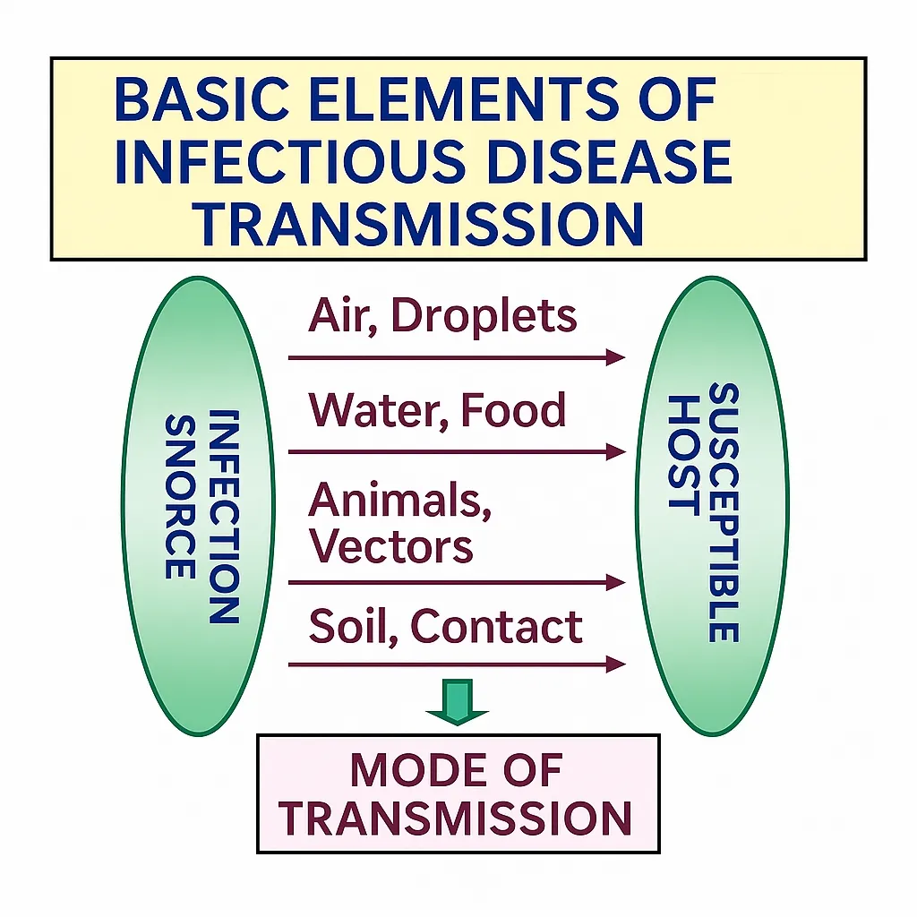
The epidemic model shown above is a close analogy:
02 Common units for electromagnetic noise
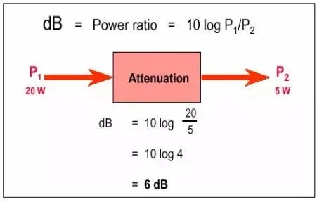
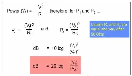
Noise is commonly expressed in decibels. The original definition of decibel is the ratio of two powers:
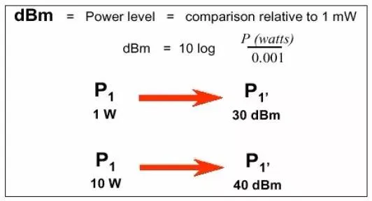
dBm is commonly used to express power; dBm is the power level relative to 1 mW:
From the following derivation, voltage in decibels can be expressed (note the assumption R1=R2):
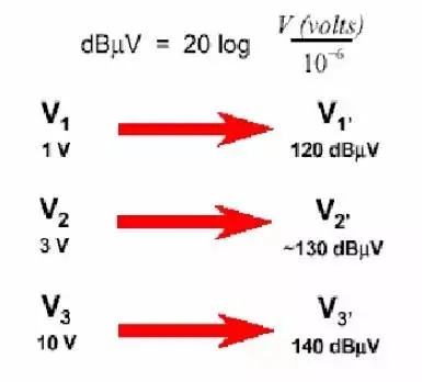
dBuV is commonly used to express voltage; dBuV is the voltage level relative to 1 μV.
For radiated noise the electromagnetic field strength is used as the metric, with units V/m. The common unit is dBuV/m.
03 Conducted interference
Common impedance coupling
Occurs when two circuits couple through a shared impedance. The interfering quantity is current i, or the changing current di/dt.
Capacitive coupling
Occurs when distributed capacitance exists between the noise source and the victim; the interfering quantity is the changing electric field, i.e., changing voltage du/dt.
Inductive coupling
Occurs when mutual inductance exists between the noise source and the victim; the interfering quantity is the changing magnetic field, i.e., changing current di/dt.
Common impedance coupling happens when ground currents of two circuits flow through a shared impedance. In amplifiers, coupling between stages using an RC coupling method is an application of signal coupling via a common impedance. In that case the output of the previous stage and the input of the next stage share an impedance. Since the ground is the return path for signals, when two circuits share a ground segment they will influence each other. One circuit's ground potential will be modulated by the ground current of the other circuit, and the other circuit's signal will couple into the first circuit. The same problem occurs for two circuits sharing a power supply. Solutions include providing separate supplies for each circuit or adding decoupling networks.
Methods to suppress resistive (common impedance) coupling
- Make the two current loops or systems independent. Keep signals separate and avoid connections that form circuit coupling.
- Limit coupling impedance; the lower the coupling impedance the better. When coupling impedance approaches zero, this is circuit decoupling. To minimize coupling impedance, conductor resistance and conductor inductance should be kept as low as possible.
- Circuit decoupling: connect different current loops electrically at only a single point. At that single point circuit interference currents cannot flow between loops, achieving loop decoupling.
- Isolation: for systems with large level differences (for example signal transmission equipment and high-power electrical equipment), adopt isolation techniques.
Capacitive coupling
Capacitive coupling occurs when distributed capacitance exists between the noise source and the victim; the interfering quantity is the changing electric field, i.e., du/dt.
Methods to suppress capacitive coupling
To suppress capacitive interference take the following measures:
- Design the source system so that voltage amplitude and rate of change are as small as possible.
- Design the victim system to have as low an impedance as possible.
- Arrange the coupling regions to minimize coupling capacitance. For wiring and cabling, maximize spacing, keep conductors short, and avoid parallel routing.
- Apply electrical shielding to separate the conductor surface of the source from that of the victim, minimizing coupling capacitance.
Example: capacitive coupling suppression
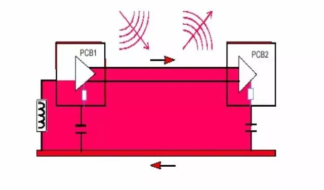
In a BUCK circuit there is a high-frequency switching node (Phase or SW node). The node's dv/dt generates an electric field, radiates, and also produces common-mode current which can be a significant component in conducted tests, especially in CISPR25 testing. High-frequency switching nodes are often related to radiated emissions, particularly in monopole and biconical antenna tests. In monopole testing, the near-field electric field from the switching node can be directly received by the antenna. To suppress dv/dt at the switching node, first reduce the area to lower near-field electric strength. As shown below, reducing SW copper area noticeably reduces the electric field strength. The same approach applies in monopole testing by reducing SW copper or inductor volume. Previously we noted that inductors cannot maintain a stable potential and are also high-frequency switching nodes.
Inductive coupling
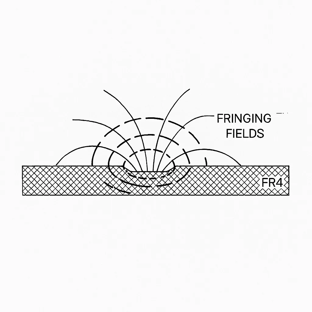
Inductive coupling arises from mutual inductance between the noise source and the victim; the interfering quantity is the changing magnetic field, i.e., di/dt. When a signal propagates along a transmission line, electric and magnetic fields form between the signal path and its return path. For example, the cross-section of a 50 Ω microstrip on FR4 shows electric and magnetic field lines that extend beyond the area directly under the trace into surrounding space. These extended fields are called fringe fields.
Fringe fields: according to electromagnetic field theory, changing electric fields induce currents and changing magnetic fields induce voltages. When wiring of a static network enters the fringe field of a dynamic network, changes in voltage and current on the dynamic network will change the fringe fields, which in turn induce noise voltage or current on the static network. This is the physical origin of crosstalk. The coupling between networks via fields can be divided into capacitive and inductive coupling, with the coupling capacitance and coupling inductance referred to as mutual capacitance and mutual inductance. Both contribute to crosstalk and must be treated separately. When the return path is a wide uniform plane, such as PCB routing, capacitive and inductive coupling are roughly comparable. Thus, to accurately predict crosstalk on coupled transmission lines, both factors must be considered. If the return path is not a wide uniform plane, such as a lead, although both couplings exist, crosstalk is primarily due to mutual inductance. In that case, a rapidly changing current on the dynamic network, such as rising or falling edges, will create significant noise on the static network.
Methods to suppress inductive coupling
- Design the source system so that the amplitude and rate of change of current are as small as possible. The victim system should present high impedance.
- Reduce mutual inductance by keeping wires short, increasing spacing, avoiding parallel runs, and, when using a two-wire structure, minimizing the area enclosed by the current loop.
- Provide magnetic shielding for the source or victim to suppress interfering magnetic fields.
- Use balancing measures so that induced interference signals cancel. For example, place the victim wire loop so it cuts the magnetic field minimally (loop direction parallel to magnetic field lines), or twist source conductors so their generated fields cancel.
Example: suppressing noise from high-frequency current loops
High-frequency current loops behave like magnetic dipoles; the magnetic moment and field strength increase with current and loop area, so noise can be reduced by lowering current or reducing area. First identify high-frequency loop topologies. In the figure below, red loops indicate regions with large di/dt. In BUCK circuits the high-frequency current loop exists in the closed loop formed by the input capacitor and the two switching devices; in BOOST circuits the loop exists in the output capacitor and two switching devices as the dual topology. In SEPI C circuits the high-frequency loop exists among the switching devices and two capacitors. High-frequency loops typically form between switching devices and the capacitors connected to them, because current changes most abruptly between switching devices while inductors limit di/dt and are not the primary focus for high-frequency loop analysis.
04 Common-mode and differential-mode interference
Common-mode interference: interference currents on two conductors that have the same amplitude and the same direction.
Differential-mode interference: interference currents on two conductors that have the same amplitude but opposite directions.
Common mode refers to currents that are the same polarity on two or more conductors. Differential mode refers to currents that are opposite polarity on a conductor pair. Common-mode interference currents have the same amplitude and phase on all conductors of a cable and form a loop between the cable and earth. Differential-mode interference currents flow between the signal conductor and its return conductor. Because the current flow patterns differ between common-mode and differential-mode interference, filtering strategies differ. Therefore, before designing filters, identify the type of interference present.
Voltage and current transmitted along conductors appear in two forms: common mode and differential mode. Power lines, telephone lines, communication lines, and other connections that exchange signals or power usually have at least two conductors to form the send-and-return path. In addition to those two conductors there is often a third conductor, the ground. Interference voltages and currents are of two types: one where the two conductors themselves form the send-and-return path (differential mode), and another where the two conductors form the forward path and ground is the return (common mode). Crosstalk (differential-mode interference) occurs between two PCB traces, while common-mode interference refers to potentials between the pair of traces and the PCB ground that cause interference.
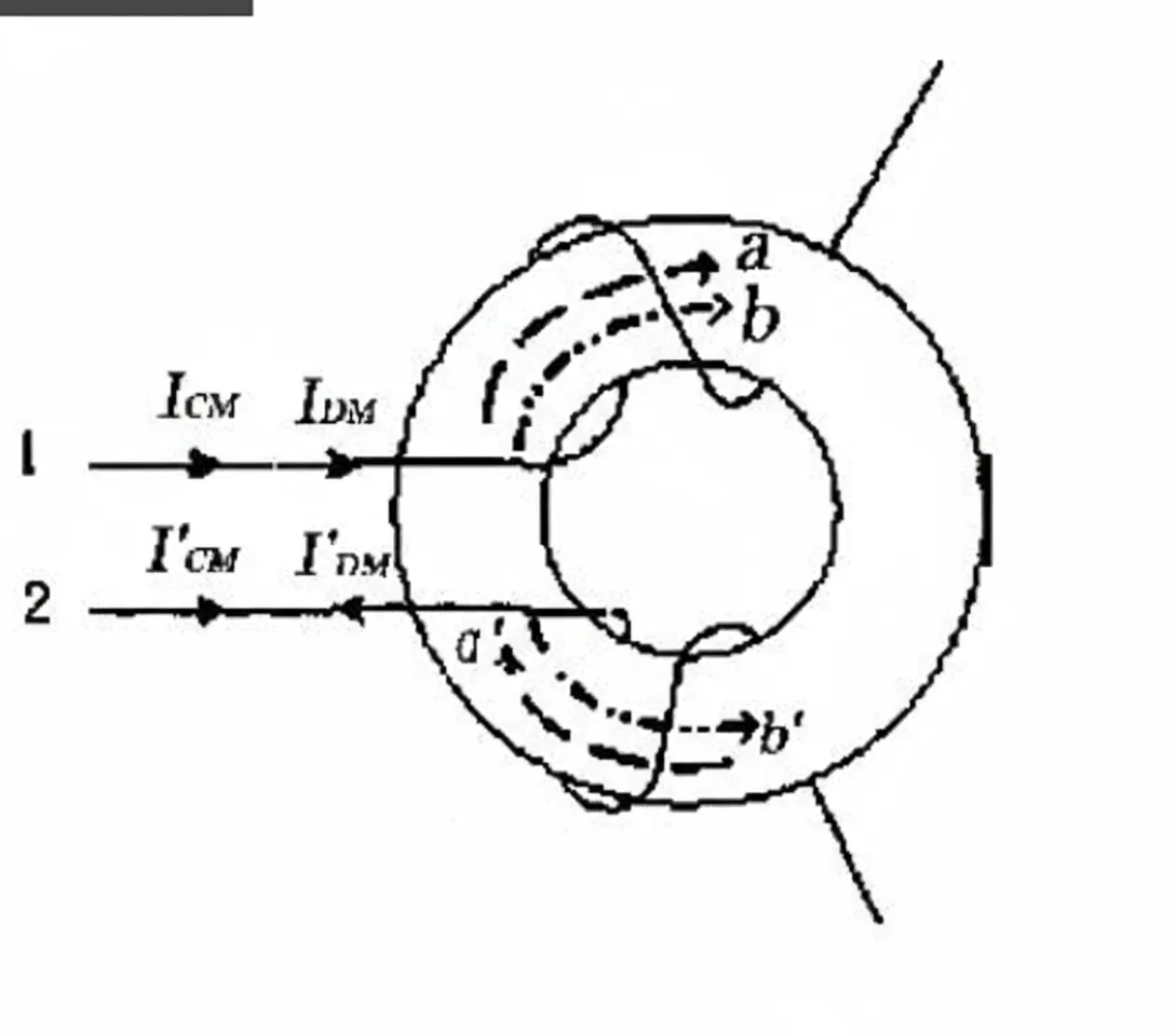
Choke coils
The primary method to suppress common-mode interference is a common-mode choke. A common-mode choke is the inductive element that dominates common-mode insertion loss. It is constructed by winding equal numbers of turns in opposite directions on the two halves of a magnetic ring or closed magnetic path.
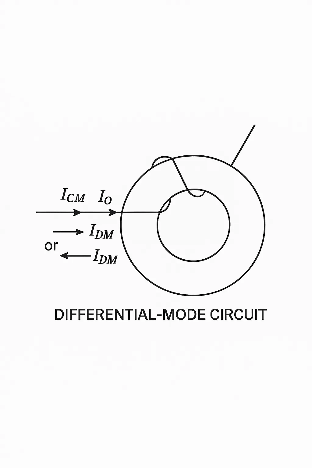
Differential-mode interference refers to interference between the signal line and its return. The interfering loop current flows in the loop formed by the conductor and its return. The main method to suppress differential-mode interference is a differential-mode choke. A differential-mode choke is the inductive element that dominates differential-mode insertion loss. It uses a single-winding structure rather than two identical windings on the same core as in a common-mode choke.
05 What is common-mode residual voltage
Common-mode voltage: the average phasor voltage appearing between each conductor and a specified reference point, often earth or chassis. In other words, it is the portion of the input voltage that is common to both measurement terminals relative to the common reference.
Differential-mode (symmetrical) voltage: the voltage between any two conductors in a specified set of conductors, also called symmetrical voltage.
For standardized waveforms, the peak voltage measured across a varistor under a specified discharge current is called residual voltage. The ratio of residual voltage to varistor voltage is the residual voltage ratio. Lightning and surge events can generate transient high voltages and large currents on input/output power lines, affecting equipment stability or causing damage. Surge protective devices are connected either in differential-mode configuration (between lines or line and neutral, called lateral protection) or in common-mode configuration (between line and earth or neutral and earth, called longitudinal protection).
Eliminating common-mode interference
- Use shielded twisted pair cable and provide effective grounding.
- Route wiring away from high-voltage lines; do not bundle high-voltage power lines with signal lines.
- Use linear regulators or high-quality switch-mode power supplies with low ripple.
- Use differential circuitry.
- Insert common-mode chokes in signal or power lines; place capacitors between ground and conductors to form LC filters to suppress common-mode conducted noise.
Eliminating differential-mode interference
- First reduce common-mode interference, since common-mode can convert to differential-mode.
- Use differential-mode chokes.


