 ALLPCB


1. Common Types of Platform Screen Doors
- Automatic platform screen door. The motor serves as the drive source, driving a worm gear or similar mechanism to open and close the door. Compared with hydraulic or pneumatic systems, a full-gear transmission system offers good stability, low noise, and no contamination. Door frames can be fitted with coded locks or IC card locks, and can interface with various electronic access control systems to coordinate automatic opening and closing.
- Pneumatic sliding platform screen door. This offers multiple control modes, easy operation, and reliable performance. The switching operation does not occupy the interior space of the shielded room, making it suitable for welded or assembled installations. Control options include automatic (IC card control), fully automatic (button control), and manual. It supports anti-pinch control and a full electrical control system using reliable timing logic for automatic operation, with custom logic available.
- Electrically clamped platform screen door. This type provides good shielding and stability, but opening and closing can be relatively heavy. It uses a full-gear transmission system with a motor as the drive source. Speed reduction and rotational motion are converted into reciprocating or ramp motion by gear mechanisms. A rack-and-pinion driven reciprocating motion and ramp mechanism complete locking and unlocking; movement is stable and quiet. When the door leaf reaches a set angle, an open/close signal triggers the door action.
2. Power and Lighting Design for Shielded Rooms
- The power supply for an electromagnetic shielded room should cover the electrical consumption of equipment inside the room and the units under test, with reserved capacity and the possibility for future expansion.
- The power and lighting design for an electromagnetic shielded room should comply with China's current applicable standards and regulations. When high-power equipment is used inside the chamber, a dedicated control circuit is recommended.
- Install a power switch for the shielded room at an appropriate exterior location. The exterior main switch should not be equipped with residual current protective devices.
- Route power lines into the shielded room through power line filters mounted on both sides of the shielding boundary.
- The filter's rated voltage, current, and frequency should be determined based on the circuit's operating voltage, calculated current, and frequency. The rated voltage of the power filter should be at least 1.2 times the calculated voltage.
- For shielded rooms requiring three-phase four-wire power, install filters on the live, neutral, and midpoint; the PE conductor should not be introduced into the shielded room.
- If a PE conductor must be introduced, only one PE conductor should enter each shielded room, and its cross section must not be smaller than the largest PE conductor in the original circuit.
- The attenuation rating of the power filter should be consistent with the shielding performance of the room.
- Lighting inside the shielded room should meet the requirements of the current National Standard GB50034 "Lighting Design Standard for Buildings." Select lamp types that have good selectivity and minimal impact on the power grid. Lighting fixtures used for measuring radiated characteristics should have low electromagnetic radiation.
- For magnetic shielding rooms, distribution equipment and lighting circuits should preferably use copper-core conductors.
3. Differences Between Shielded Rooms and Anechoic Chambers
A shielded room is essentially a metal enclosure that blocks wireless communication signals between the interior and exterior. In other words, signals inside cannot escape and external signals cannot enter. However, electromagnetic waves inside a shielded room can reflect and accumulate on internal surfaces.
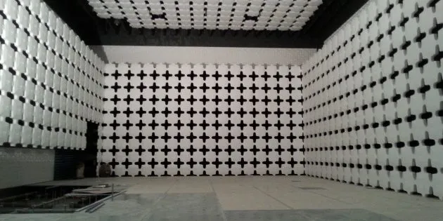
An electromagnetic anechoic chamber augments a shielded room by lining the interior with absorptive materials to simulate free-space conditions. Anechoic chambers are significantly more expensive than basic shielded rooms, largely due to the absorptive materials used. Electromagnetic waves inside an anechoic chamber are absorbed rather than reflected, minimizing multipath interference and making the chamber suitable for measuring radiated emissions. Anechoic chambers are generally classified as full anechoic chambers and semi-anechoic chambers.
For tests that do not require strict free-space conditions—such as conducted interference, electrostatic discharge, surge, or lightning immunity—testing can often be performed in a shielded room using power connections. However, tests concerning spatial radiating sources or field disturbances that depend on free-space propagation require an anechoic chamber to simulate a wide open environment.
Full anechoic chambers, semi-anechoic chambers, and open-area test sites are the three common test environments that can approximate free-space propagation. Full anechoic chambers reduce external electromagnetic interference and, because of wall and ceiling absorption, minimize multipath effects on test results. They are suitable for emissions, sensitivity, and immunity testing. If the shielding effectiveness of the enclosure is between 80 dB and 140 dB, and external influences are controlled, a full anechoic chamber can effectively simulate free space. Full anechoic chambers have lower surface reflections compared with the other two environments, are less affected by external conditions, and are not influenced by external temperature. The main limitation is the cost and finite test volume.
A semi-anechoic chamber is similar to a full anechoic chamber in that it is a shielded enclosure lined with absorptive materials on walls and ceiling; the difference is that a conductive floor is used instead of floor absorbers. The semi-anechoic chamber simulates an ideal open-site condition with an infinite conductive ground plane. Because the floor is reflective, a received signal consists of direct and ground-reflected paths.
An open-area test site is a flat, large, conductive, and reflection-free field such as an oval or circular test ground. In an ideal open site the ground plane is perfectly conductive and of infinite extent, and between 30 MHz and 1000 MHz the received signal is the sum of the direct and reflected paths. In practice, while good ground conductivity can be achieved, the overall site area is limited, which can introduce phase differences between transmit and receive antennas. For emission testing, open-area sites and semi-anechoic chambers are used similarly. Every EMC test report specifies the test environment; radiated emission and radiated immunity tests typically have stricter site requirements because propagation in the 80 MHz to 1000 MHz band is governed by the superposition of direct and ground-reflected waves at the receiver.
Nonideal test sites inevitably produce measurement deviations. Open-area test sites are the reference environments for EMC testing, but construction costs and the need to avoid populated areas make them less accessible. Indoor shielded rooms are often used instead. However, a closed metallic shielded enclosure can support many resonant modes. If the radiating frequency and excitation of the device under test coincide with chamber resonances, measurement errors of 20 to 30 dB can occur. Therefore, absorptive materials should be installed on the chamber walls and ceiling to reduce reflections, leaving primarily direct and ground-reflected waves. Such facilities are electromagnetic shielded absorptive chambers, commonly termed EMC anechoic chambers.
Standards such as FCC, ANCIC63.6-1992, IEC, CISPR, and military standards GJB152A-97 and GJB2926-97 permit certain semi-anechoic shielded chambers to be used in place of open-area test sites for EMC testing. An EMC anechoic chamber typically consists of an RF shielded enclosure, absorptive materials, power supplies, antennas, and a turntable. RF shielding, ventilation waveguide ports, surveillance cameras, lighting fixtures, and power boxes should be placed outside the primary reflection zone to avoid exposing metallic components within the main reflection area. The chamber floor serves as the vertical conductive plane.
Requirements for the floor include continuous flatness with no gaps exceeding one-tenth of the working wavelength to maintain conductive continuity. Cable entries and power outlets inside the chamber should be located at the walls and should not cross the test area. Cables should be routed through metal conduits with good electrical bonding between the conduits and the conductive floor. To avoid measurement errors caused by reflections, personnel and control equipment should remain outside the test area. EMC facilities typically consist of a test chamber and a control room; antennas and the device under test are placed in the chamber, while operators and test equipment remain in the control room.
If high-power amplifiers are used, a separate amplifier room should be provided to contain such equipment and prevent interference with surrounding areas. The chamber and control room should have separate power distribution systems, using different-phase power supplies and separate filters to prevent control-room noise from entering the chamber via the power lines.


