ALLPCB


Introduction
This article uses an indicative Abracon LLC unit to examine broadband antennas that serve low-band 5G spectrum and legacy bands. It shows how this type of antenna, whether a visible external unit or an embedded internal unit, can simplify design and the bill of materials (BOM) while enabling faster upgrades to 5G when needed.
Beyond consumer smartphones, 5G-based wireless links address diverse embedded applications such as Internet of Things (IoT), machine-to-machine links, smart grid, vending machines, gateways, routers, security and remote monitoring connections. The migration to 5G will be gradual. Antennas at the front end of wireless links must support both 5G and existing 2G/3G/4G links; even as 5G deployments grow, other links will coexist for years.
Why Support Multiple Bands
For these reasons, engineers designing products must consider support for legacy bands in addition to bands required by 5G standards. Even if the RF front ends or power amplifiers for each band differ, using a single broadband antenna to serve both 5G and legacy bands offers multiple practical advantages.
Power-Rail Management Challenges
Antennas are the final element in the RF transmit path and the first element in the complementary receive path. Their role is to transduce between the circuit world of currents and voltages and the RF world of radiated energy and electromagnetic fields.
When selecting an antenna for a target application, remember that an antenna's operation is independent of the modulation type or industry standard being used. Typical selection parameters include center frequency, bandwidth, gain, rated power and physical size, but none depend on whether the antenna will be used for amplitude, frequency or phase modulation (AM, FM, PM), or for 3G, 4G, 5G or proprietary formats.
System designs aimed at supporting new 5G standards tend to get significant attention, particularly for the sub-6 GHz 5G bands used by many current deployments. It is important to distinguish the wireless standards a system supports from the frequencies and spectrum that determine the antenna choice.
New 5G standards use previously unavailable spectrum while also using more advanced modulation schemes in existing spectrum to increase throughput. Thus, although an industry standard may be phased out, the spectrum it occupies can still be used by newer standards. In practice, antennas that support 3G or 4G bands can often be suitable for 5G and vice versa. Reusing antennas that support multiple standards and bands is a practical and often desirable solution.
Supported Frequency Ranges and Examples
Important standards within the 600 MHz to 6 GHz RF spectrum include:
- Citizens Broadband Radio Service (CBRS), roughly 3550 MHz to 3700 MHz (3.55–3.7 GHz), a 150 MHz lightly regulated band shared among incumbent users, priority access license (PAL) users and general authorized access (GAA) users in some jurisdictions.
- LTE-M (LTE Cat-M1), a low-power wide-area technology that enables battery-powered IoT devices to connect directly to 4G networks without a gateway.
- Narrowband IoT (NB-IoT), a low-data-rate cellular technology using OFDM within the 3GPP framework for extremely low-power, battery-operated devices.
Note on terminology: "wideband" refers to an antenna whose bandwidth is a substantial fraction of its center frequency, informally at least 20%–30% of the center frequency. "Multiband" means the antenna design supports two or more regulatory bands, which may be closely spaced or widely separated. A multiband antenna may but does not necessarily qualify as a wideband antenna. Multiband antennas typically have a single RF connection even if they combine multiple internal radiator elements. Unlike simple wideband antennas, multiband designs may intentionally leave gaps in gain coverage across the spectrum to minimize co-band interference.
Built-in vs External Antennas
Frequency and bandwidth impact the physical implementation of antennas and therefore are important design decisions. One key choice is whether to use an external antenna or an embedded internal antenna.
Embedded antennas:
- Create a sleeker enclosure with no external attachments that could break or snag
- Remain permanently connected and available
- Are constrained in coverage, efficiency, radiation pattern and other performance metrics
- Have performance that is sensitive to adjacent circuitry and PCB layout
- Can have radiation patterns and efficiency altered by a user’s hand or body
External antennas:
- Allow more freedom to optimize radiation pattern, bandwidth and gain
- Can be positioned away from the RF unit using coaxial cable for optimal placement
- Are less affected by the product’s internal PCB layout
- Come in a variety of styles and configurations
- Require a connector or cable for connection, which can be a potential failure point
Choice depends on factors such as final product use, user preferences, performance trade-offs and whether the device is mobile or fixed. A smartphone with an external antenna is usually undesirable, whereas a fixed IoT node with an external antenna may provide more stable connectivity.
Benefits of Multiband Antennas
Multiband antennas meet current application requirements and provide a pathway for future upgrades including 5G. Key benefits include:
- One antenna can serve a product family across bands, simplifying inventory and procurement
- Embedded multiband antennas enable smaller enclosures, while external multiband antennas reduce the number of antenna connectors on the enclosure
- Multiband antennas can serve IoT devices expected to upgrade to new bands due to performance needs or legacy band deprecation
- A single external antenna for multiple bands maintains common installation practices and tooling
- For critical fixed and mobile applications, RF subsystems can provide dual-band support and dynamically switch bands for optimal performance
- Designers can reuse a single embedded multiband antenna across unrelated devices, leveraging experience in modeling, placement and production
Real Multiband Antenna Examples
Multiband antennas vary in form factor and termination options. The following examples illustrate typical performance and mechanical choices.
AEBC1101X-S Whip Antenna
The AEBC1101X-S is a 5G/4G/LTE cellular whip antenna, 115 mm long and 19 mm maximum diameter, designed to operate from 600 MHz to 6 GHz. It is fitted with a standard male SMA connector that can rotate 90° for direct mounting to the enclosure (also usable with a coaxial extension cable); reverse-polarity SMA connectors are available as an option.
600 MHz to 6000 MHz supports multiple standards such as 3G, 4G and 5G, with some spectrum overlap.
| Parameter | Specification | |
| Operating Frequency | 600 MHz – 900 MHz, 1710 MHz – 2690 MHz, 3300 MHz – 6000 MHz | |
| Polarization | Linear | |
| Impedance | 50 Ω | |
| Supported Bands | 5G NR | n1, n2, n3, n5, n6, n7, n12, n14, n18, n20, n25, n28, n29, n30, n34, n38, n39, n40, n41, n65, n66, n70, n71, n77, n78, n79, n80, n81, n82, n83, n84, n86, n89, n90, n95 |
| 4G LTE | B1, B2, B3, B4, B5, B7, B8, B12, B13, B14, B17, B18, B19, B20, B25, B26, B28, B29, B34, B37, B38, B39, B41, B42, B43, B44, B48, B49, B52, B65, B66, B67, B68, B69, B70, B71, B85 | |
| 3G | PCS, DCA, UMTS | |
VSWR and peak gain remain fairly stable across the band, with efficiency variations between low and high ends.
|
|||||||||||||||||||||||||||||||||||||||||||||||
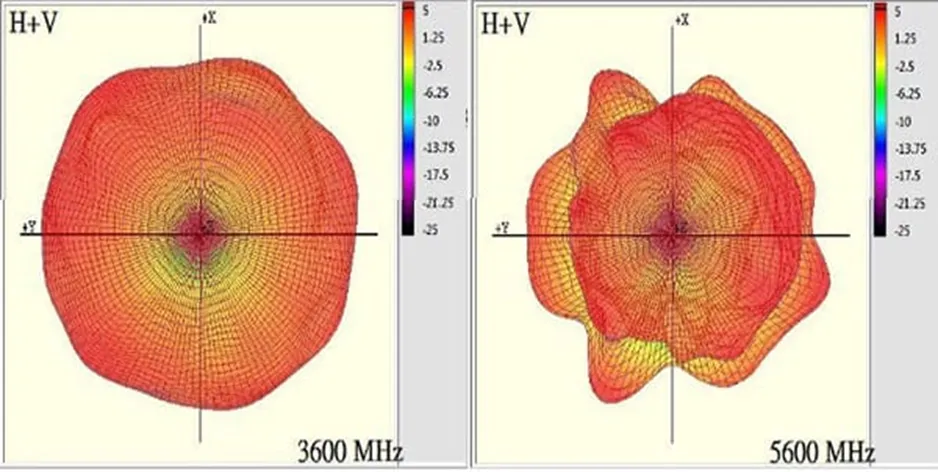
The radiation pattern is nearly circular across the band, with some small lobes around 3600 MHz that become more pronounced near 5600 MHz.
AECB1102XS-3000S Blade Antenna
The AECB1102XS-3000S blade antenna covers 600 MHz to 6 GHz and measures 115.6 mm × 21.7 mm with a slim 5.8 mm thickness. It is intended for flat-surface mounting using tape for simple installation.
The AECB1102XS-3000S blade antenna is a low-profile antenna for 600 MHz to 6 GHz operation and is suited for adhesive mounting on flat surfaces.
Its RF performance is similar to the AEBC1101X-S, with a maximum VSWR below 3.5 and a peak gain around 2 dBi, slightly lower than a typical omnidirectional radiator. The X-Y and X-Z plane radiation patterns are more complex than the whip antenna’s patterns.
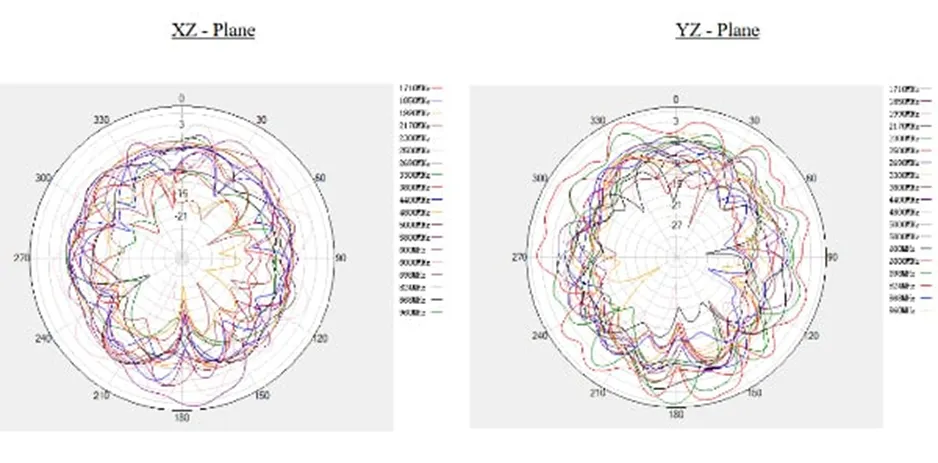
AECB1102XS-3000S X-Z and Y-Z patterns show a set of lobes more complex than the whip antenna.
A notable difference between AEBC1101X-S and AECB1102XS-3000S is termination. The AECB1102XS-3000S blade unit ships with a 1 m LMR-100 coaxial cable and a standard male SMA connector. Cable lengths and other connector types are available as standard options to support flexible installations.
| Cable and Connector Options | ||
| Code | Cable Type | Connector Type |
| S (Standard) | LMR-100 | SMA (M) |
| A | FAKRA-D (F) | |
| B | RP-SMA (M) | |
| C | SMB (M) | |
| D | Type N (M) | |
| E | TNC (M) | |
| F | BNC (M) | |
| G | MCX (M) | |
| H | MMCX (M) | |
| I | FME (M) | |
| J | FME (F) | |
The AECB1102XS-3000S ships with an LMR-100 coax and male SMA connector, with other connector options available.
ACR4006X Ceramic Patch Surface-Mount Antenna
The ACR4006X is a 600 MHz to 6000 MHz wideband ceramic patch antenna in a compact 40 × 6 × 5 mm surface-mount package. It requires a small LC impedance-matching network on the PCB: an 8.2 nH inductor and a 3.9 pF capacitor (both 0402) to achieve the required 50 Ω match.
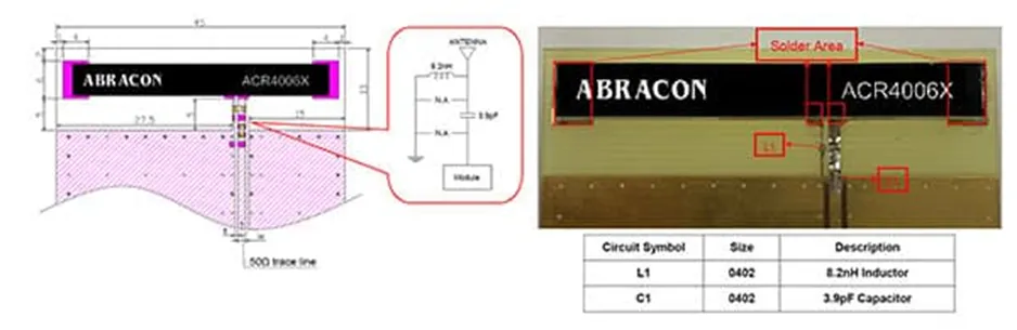
The ACR4006X ceramic patch antenna base measures 40 × 6 mm and requires only two small passive components for 50 Ω matching.
The datasheet describes the ACR4006X as a 600–6000 MHz device, but note the efficiency and gain plots show intentional gaps. The device was optimized for three specific bands within that range: 600–960 MHz, 1710–2690 MHz and 3300–6000 MHz, covering common 3G, 4G and 5G allocations and smaller spectrum blocks.
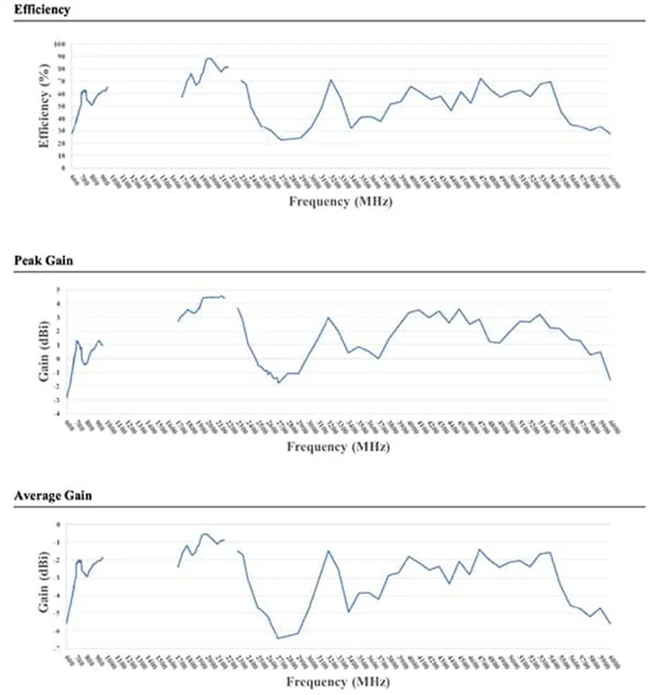
ACR4006X efficiency and gain plots show gaps outside the primary target bands; these gaps do not affect the intended 3G, 4G and 5G operating bands.
The ACR4006X is not intended for GPS reception and has no specified performance at GPS L1 (1575.42 MHz) or L2 (1227.6 MHz) carrier frequencies.
The X-Y radiation pattern of the ACR4006X varies with frequency but remains roughly circular across the wide band, with some frequency-dependent dips near 90° and 270°.
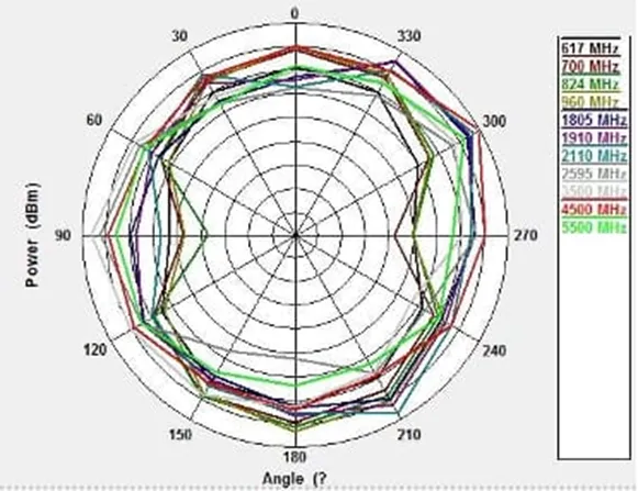
ACR4006X X-Y pattern is approximately circular with some frequency-dependent dips at 90° and 270°.
Performance evaluation begins with the datasheet, proceeds to anechoic chamber validation and concludes with field testing in the final product. Factors that affect external antenna performance include enclosure, user body interaction and antenna placement. Embedded units such as the ACR4006X are influenced by adjacent PCB components and layout. Abracon provides the ACR4006X-EVB evaluation board to accelerate engineering evaluation of this patch antenna.
The evaluation board is used with a vector network analyzer (VNA). After standard calibration, the antenna performance is assessed through the board’s SMA connector using the VNA’s calibrated port. The evaluation board is precisely 120 × 45 mm to ensure correct placement of the patch antenna and includes the required 45 × 13 mm ground clearance around the antenna for normal operation.
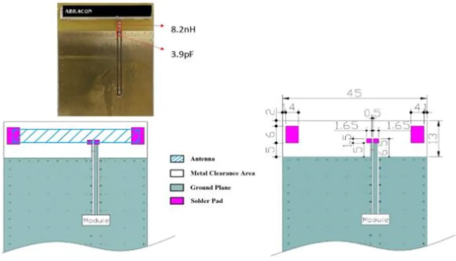
The ACR4006X-EVB evaluation board measures 120 × 45 mm and provides the SMA connector and recommended layout for antenna evaluation.
Conclusion
Multiband antennas address many challenges faced by IoT and embedded devices that must support existing single bands while offering smoother upgrade paths to newer standards such as 5G. These antennas enable systems to operate across multiple bands to improve connectivity in areas where a single band is insufficient. Embedded antennas mounted on PCBs enable sleeker enclosures, while external antennas with integrated connectors or coaxial cable attachments offer placement flexibility to achieve optimal signal paths.