ALLPCB


Suffix meaning recap
None Single Carrier
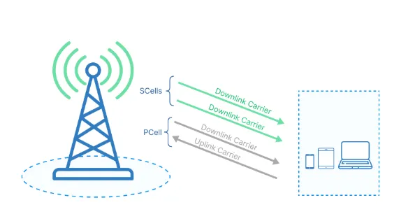
A Carrier Aggregation (CA)
B Dual-Connectivity (DC)
C Supplement Uplink (SUL)
D UL MIMO
E V2X
F Shared spectrum channel access
G Tx Diversity (TxD)
I RedCap
Chapters labeled with 6.5 previously covered single carrier spectrum emissions. By the above convention, 6.5A refers to the CA portion of spectrum emissions. Before studying CA spectrum emissions, the CA-supported bands, component carrier combinations, and CA bandwidth definitions must be clarified.
CA band combinations
To date, 3GPP defines 53 FR1 bands from n1 to n101. The listings below show uplink (UL) first and downlink (DL) second.
n1  1920 MHz - 1980 MHz  2110 MHz - 2170 MHz  FDD
n2  1850 MHz - 1910 MHz  1930 MHz - 1990 MHz  FDD
n3  1710 MHz - 1785 MHz  1805 MHz - 1880 MHz  FDD
n5  824 MHz - 849 MHz  869 MHz - 894 MHz  FDD
n7  2500 MHz - 2570 MHz  2620 MHz - 2690 MHz  FDD
n8  880 MHz - 915 MHz  925 MHz - 960 MHz  FDD
n12  699 MHz - 716 MHz  729 MHz - 746 MHz  FDD
n13  777 MHz - 787 MHz  746 MHz - 756 MHz  FDD
n14  788 MHz - 798 MHz  758 MHz - 768 MHz  FDD
n20  832 MHz - 862 MHz  791 MHz - 821 MHz  FDD
n24  1626.5 MHz - 1660.5 MHz  1525 MHz - 1559 MHz  FDD
n25  1850 MHz - 1915 MHz  1930 MHz - 1995 MHz  FDD
n26  814 MHz - 849 MHz  859 MHz - 894 MHz  FDD
n28  703 MHz - 748 MHz  758 MHz - 803 MHz  FDD
n29  N/A  717 MHz - 728 MHz  SDL
n30  2305 MHz - 2315 MHz  2350 MHz - 2360 MHz  FDD
n34  2010 MHz - 2025 MHz  2010 MHz - 2025 MHz  TDD
n38  2570 MHz - 2620 MHz  2570 MHz - 2620 MHz  TDD
n39  1880 MHz - 1920 MHz  1880 MHz - 1920 MHz  TDD
n40  2300 MHz - 2400 MHz  2300 MHz - 2400 MHz  TDD
n41  2496 MHz - 2690 MHz  2496 MHz - 2690 MHz  TDD
n46  5150 MHz - 5925 MHz  5150 MHz - 5925 MHz  TDD
n47  5855 MHz - 5925 MHz  5855 MHz - 5925 MHz  TDD
n48  3550 MHz - 3700 MHz  3550 MHz - 3700 MHz  TDD
n50  1432 MHz - 1517 MHz  1432 MHz - 1517 MHz  TDD
n51  1427 MHz - 1432 MHz  1427 MHz - 1432 MHz  TDD
n53  2483.5 MHz - 2495 MHz  2483.5 MHz - 2495 MHz  TDD
n65  1920 MHz - 2010 MHz  2110 MHz - 2200 MHz  FDD
n66  1710 MHz - 1780 MHz  2110 MHz - 2200 MHz  FDD
n70  1695 MHz - 1710 MHz  1995 MHz - 2020 MHz  FDD
n71  663 MHz - 698 MHz  617 MHz - 652 MHz  FDD
n74  1427 MHz - 1470 MHz  1475 MHz - 1518 MHz  FDD
n75  N/A  1432 MHz - 1517 MHz  SDL
n76  N/A  1427 MHz - 1432 MHz  SDL
n77  3300 MHz - 4200 MHz  3300 MHz - 4200 MHz  TDD
n78  3300 MHz - 3800 MHz  3300 MHz - 3800 MHz  TDD
n79  4400 MHz - 5000 MHz  4400 MHz - 5000 MHz  TDD
n80  1710 MHz - 1785 MHz  N/A  SUL
n81  880 MHz - 915 MHz  N/A  SUL
n82  832 MHz - 862 MHz  N/A  SUL
n83  703 MHz - 748 MHz  N/A  SUL
n84  1920 MHz - 1980 MHz  N/A  SUL
n86  1710 MHz - 1780 MHz  N/A  SUL
n91  832 MHz - 862 MHz  1427 MHz - 1432 MHz  FDD
n92  832 MHz - 862 MHz  1432 MHz - 1517 MHz  FDD
n93  880 MHz - 915 MHz  1427 MHz - 1432 MHz  FDD
n94  880 MHz - 915 MHz  1432 MHz - 1517 MHz  FDD
n95  2010 MHz - 2025 MHz  N/A  SUL
n96  5925 MHz - 7125 MHz  5925 MHz - 7125 MHz  TDD
n97  2300 MHz - 2400 MHz  N/A  SUL
n99  1626.5 MHz - 1660.5 MHz  N/A  SUL
n100  874.4 MHz - 880 MHz  919.4 MHz - 925 MHz  FDD
n101  1900 MHz - 1910 MHz  1900 MHz - 1910 MHz  TDD
How are FR1 CA bands and their combinations defined? CA is classified three ways:
- Intra-band contiguous carrier aggregation: CA configuration is a single operating band that supports an NR CA bandwidth class.
- Intra-band non-contiguous CA: CA configuration is a single operating band that supports two or more sub-blocks, each sub-block supporting an NR CA bandwidth class.
- Inter-band CA: CA configuration is a combination of operating bands; each band supports an NR CA bandwidth class.
1. Intra-band contiguous CA: the following are available:
CA_n40
CA_n41
CA_n46
CA_n48
CA_n66
CA_n77
CA_n78
CA_n79
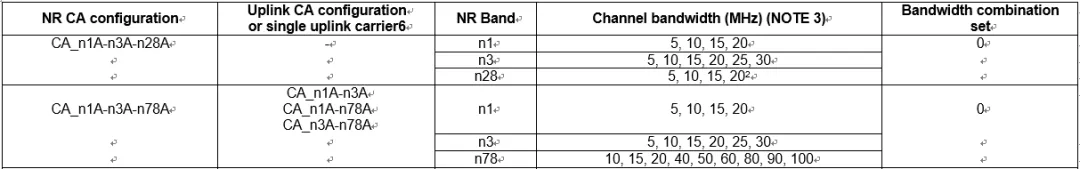
Within these, multiple specific combinations exist. The table below selects the Chinese market bands n41, n78 and n79 for examples of intra-band contiguous CA and their maximum aggregated bandwidths. Note that downlink CA and uplink CA configurations can differ. CA requires more than one aggregated carrier, but CA may be applied only in the downlink while uplink remains single carrier, or both uplink and downlink may support CA with identical or different configurations.
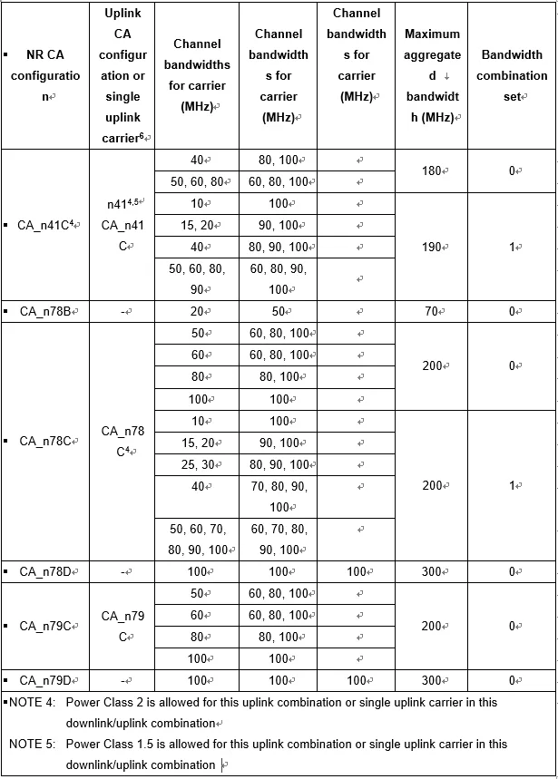
In that table, suffixes like B, C, D after a band (for example n78D) represent NR CA bandwidth classes. For instance, class D indicates bandwidth greater than 200 MHz and less than or equal to 3 × BWChannel,max. A detailed definition of CA bandwidth classes appears below.
2. Intra-band non-contiguous CA: the following are available:
CA_n2
CA_n48
CA_n66
CA_n71
CA_n77
CA_n78
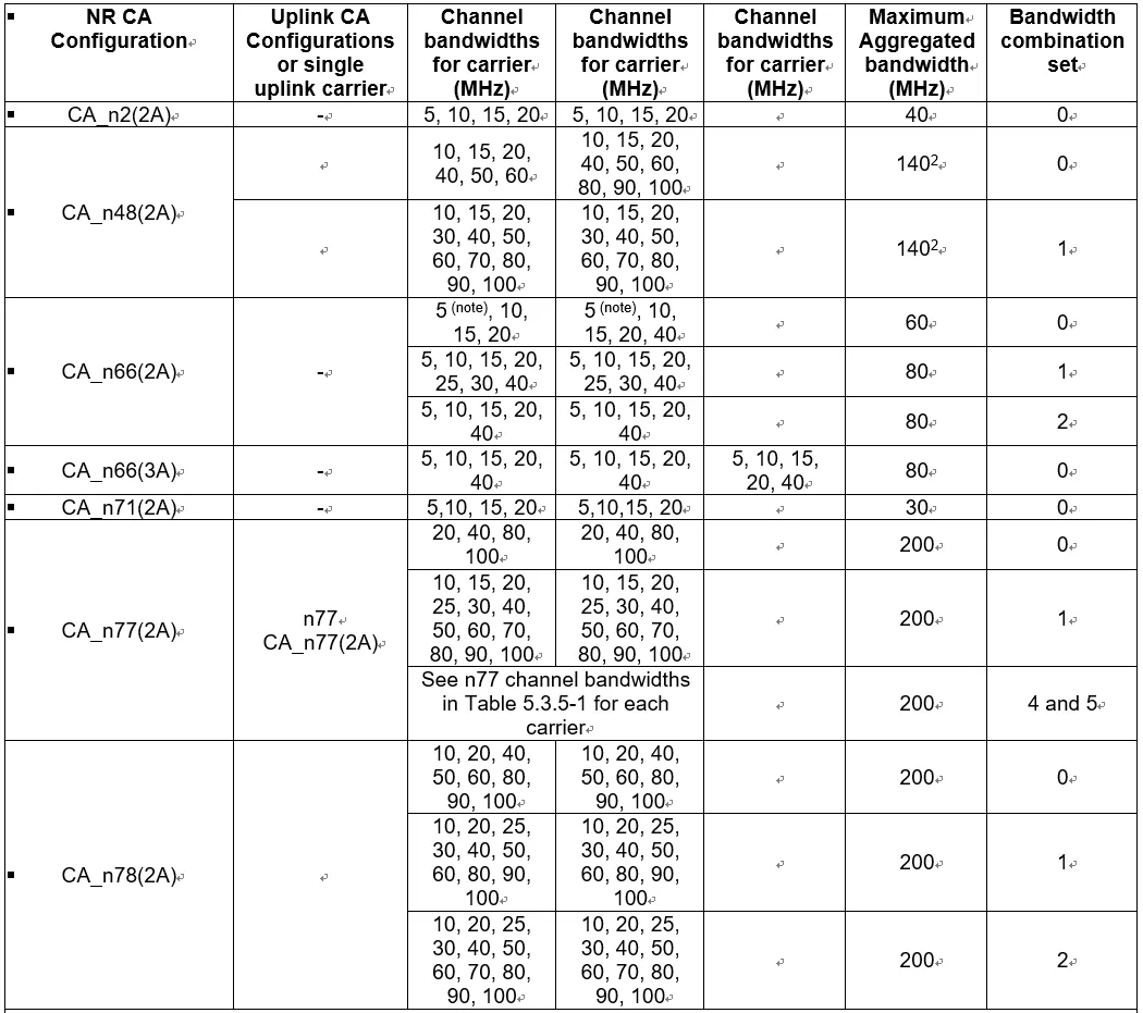
Multiple specific combinations exist; see the table below. Note that for intra-band non-contiguous CA, only n77 currently has an uplink CA configuration; other bands do not yet define UL CA. The annotations (2A) and (3A) indicate two or three non-contiguous carriers respectively.
3. Inter-band CA is defined for combinations of 2, 3, and 4 bands.
Two-band combinations are defined as follows. Most inter-band dual-carrier CA pairs pair a low band (700 MHz - 3 GHz) carrier with a mid band (3 - 5 GHz) carrier, though some pairs use two mid-band carriers (for example n78-n79).
CA_n1-n3
CA_n1-n8
CA_n1-n28
CA_n1-n77
CA_n1-n78
CA_n2-n5
CA_n2-n14
CA_n2-n48
CA_n2-n66
CA_n2-n77
CA_n3-n5
CA_n3-n8
CA_n3-n28
CA_n3-n41
CA_n3-n77
CA_n3-n78
CA_n5-n7
CA_n5-n48
CA_n5-n66
CA_n5-n77
CA_n5-n78
CA_n7-n78
CA_n8-n78
CA_n14-n30
CA_n14-n66
CA_n14-n77
CA_n20-n78
CA_n24-n41
CA_n24-n48
CA_n24-n77
CA_n25-n66
CA_n25-n77
CA_n25-n78
CA_n25-n46
CA_n26-n66
CA_n26-n70
CA_n28-n41
CA_n28-n77
CA_n28-n78
CA_n28-n79
CA_n29-n66
CA_n29-n70
CA_n29-n71
CA_n39-n41
CA_n41-n66
CA_n41-n71
CA_n41-n79
CA_n46-n48
CA_n46-n66
CA_n48-n66
CA_n48-n70
CA_n48-n71
CA_n48-n77
CA_n66-n70
CA_n66-n71
CA_n66-n77
CA_n66-n78
CA_n70-n71
CA_n71-n77
CA_n77-n79
CA_n78-n79
As an example of a configuration with CA in both uplink and downlink, consider n1-n78:
Three-band CA combinations and examples:
CA_n1-n3-n28
CA_n1-n3-n78
CA_n1-n78-n79
CA_n2-n5-n48
CA_n2-n5-n77
CA_n2-n48-n66
CA_n2-n48-n77
CA_n2-n66-n77
CA_n3-n28-n41
CA_n3-n28-n77
CA_n3-n28-n78
CA_n5-n48-n66
CA_n5-n48-n77
CA_n5-n66-n77
CA_n25-n66-n77
CA_n25-n66-n78
CA_n26-n66-n70
CA_n28-n41-n79
CA_n29-n66-n70
CA_n41-n66-n71
CA_n48-n66-n70
CA_n48-n66-n71
CA_n48-n66-n77
CA_n48-n70-n71
CA_n66-n70-n71
Four-band CA combinations and examples:
CA_n1-n3-n28-n78
CA_n2-n5-n48-n66
CA_n2-n5-n48-n77
CA_n2-n5-n66-n77
CA_n2-n48-n66-n77
CA_n5-n48-n66-n77
How CA bandwidth is calculated
First, for the maximum transmission bandwidth configuration, intra-band contiguous and intra-band non-contiguous CA follow the same requirements as single carrier; for inter-band CA, each component carrier's bandwidth must be assessed separately, and each component carrier follows the same single-carrier requirements.
Second, the calculation of the actual occupied CA bandwidth is as follows:
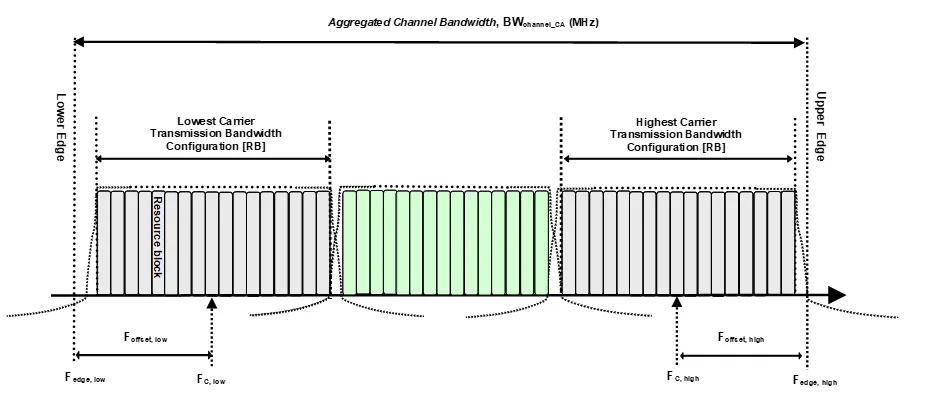
- Intra-band contiguous CA: as shown below, the aggregated channel bandwidth BWChannel_CA is defined as BWChannel_CA = Fedge,high - Fedge,low (MHz). Since carriers are contiguous, the aggregated bandwidth equals the highest edge minus the lowest edge.
- Intra-band non-contiguous CA: as shown below, because carriers are non-contiguous, the bandwidth of each contiguous sub-block must be considered. Each sub-block's bandwidth is calculated the same way as for contiguous CA.
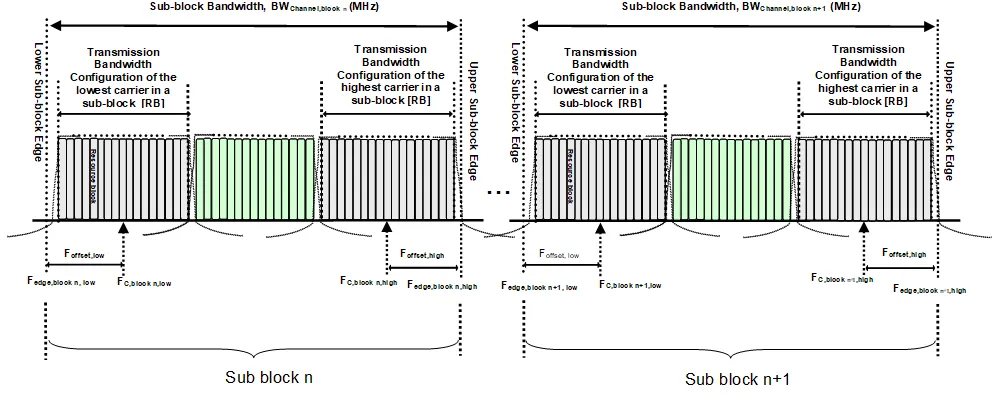
For intra-band non-contiguous CA, a frequency separation class Fs is defined to indicate, when dual-PA architecture IE signaling is absent, the maximum frequency span between the lowest edge of the lowest component carrier and the highest edge of the highest component carrier that can be supported for each band combination in UL non-contiguous intra-band operation.
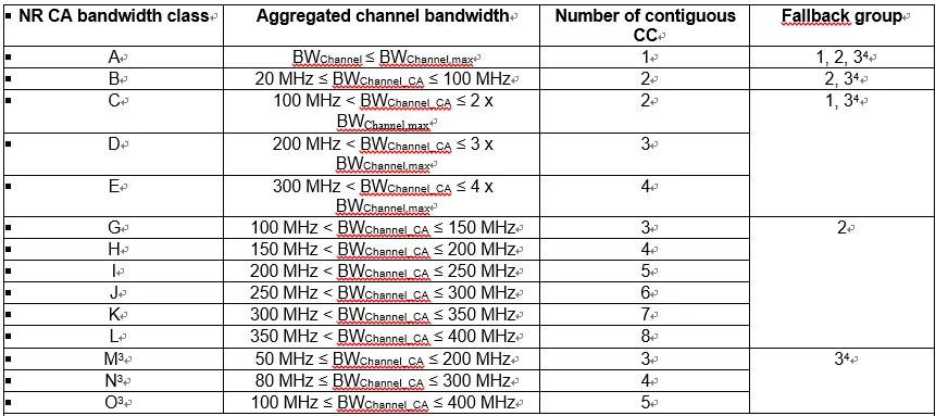
The table below defines a single operating band supporting two or more sub-blocks for intra-band non-contiguous CA. Each sub-block supports an NR CA bandwidth class. Different bandwidth classes correspond to parameters: aggregated bandwidth, number of contiguous carriers, and fallback group (UE must be able to fall back to lower NR CA bandwidth class configurations within the same fallback group, but is not required to fall back to configurations in different fallback groups).
3. For inter-band CA, the CA configuration is a combination of multiple operating bands; each band supports one of the NR CA bandwidth classes shown above.