 ALLPCB


Introduction
This article summarizes practical techniques to help meet automotive EMC requirements, including reducing emitted EMI and improving immunity to external noise. The guidance covers common automotive test standards and design practices to increase the likelihood of passing EMC/EMI testing on the first attempt.
EMC Test Standards Overview
CISPR 25 is a standard that defines test methods and suggested limits for radiated emissions from components intended for installation in vehicles. Many automakers supplement CISPR 25 with their own requirements. The primary goal of CISPR 25 testing is to ensure that a component will not interfere with other in-vehicle systems.
CISPR 25 requires the test chamber background noise to be at least 6 dB below the lowest measured level of the device under test. Because CISPR 25 anticipates background levels as low as 18 dBμV/m, the chamber must provide an environment below about 12 dBμV/m. In practice this means testing in a purpose-built, shielded room with RF-absorbing walls to avoid internal reflections. These test chambers are costly and often rented by the hour, so evaluating EMC/EMI early in the design phase can save significant time and expense.
Another common test family is ISO 11452-4 bulk current injection (BCI), which verifies immunity to narrowband electromagnetic fields by injecting disturbance currents directly into harnesses using a current probe.
Ten Tips for Designing to Pass EMC/EMI Tests
1. Keep loop areas small
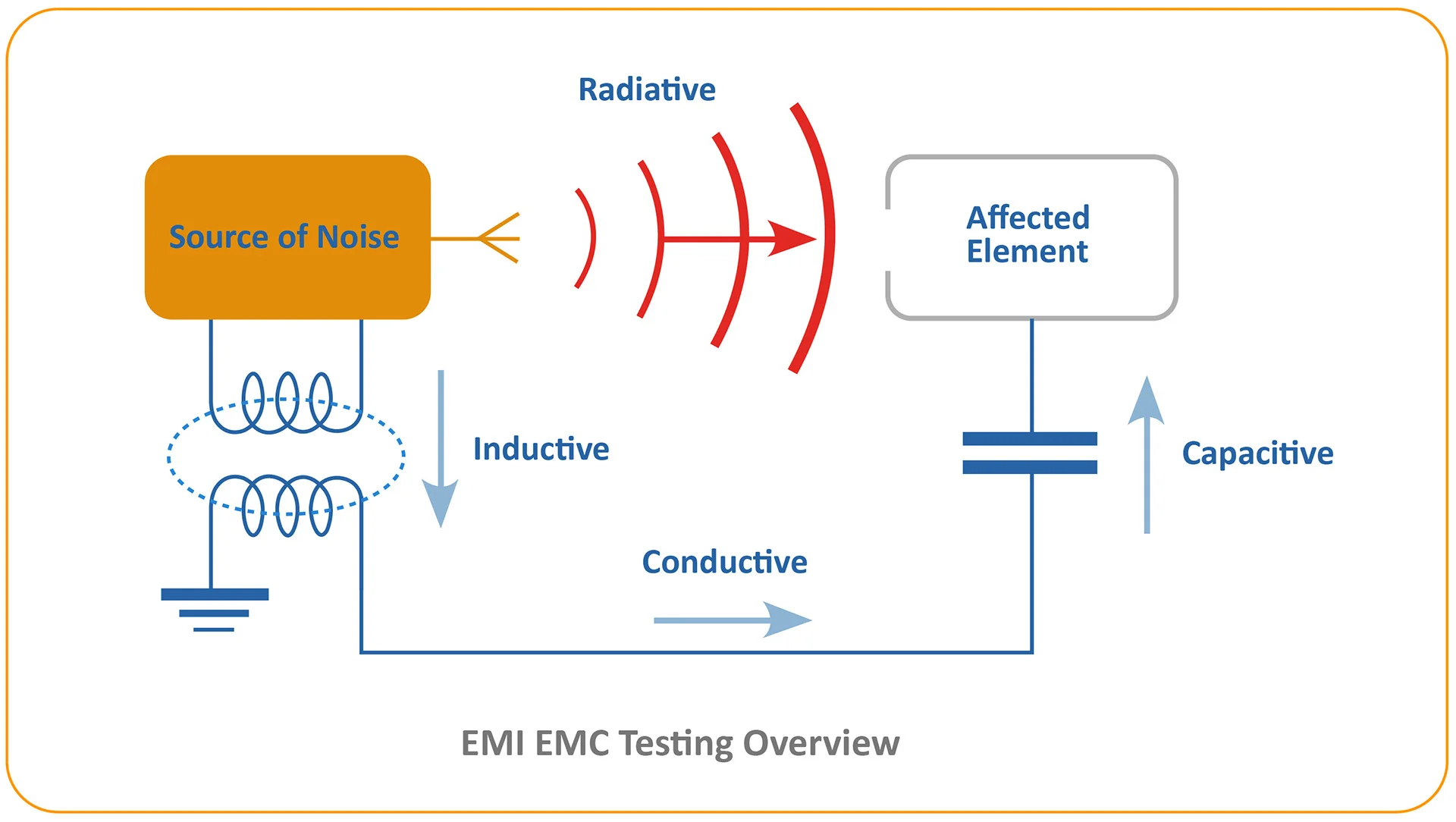
A conductive loop in a magnetic field acts like an antenna, converting the field into circulating currents. Induced current is proportional to the enclosed loop area, so minimize closed-loop areas wherever possible. Differential data paths can create loops between transmitter and receiver. Common-ground arrangements between subsystems, for example a display and its control ECU, can form large loops if separate return conductors are used. Where unavoidable, adding an in-line inductor or ferrite bead in the return path will break the loop for RF while leaving DC continuity intact.
For twisted-pair cabling, the loop area is small in the cable itself, but once the signal reaches the PCB keep the pair tightly coupled to avoid increasing the loop area on the board.
2. Place bypass capacitors close to power pins
CMOS devices draw large transient currents during switching edges, so peak currents and voltages, not average power, drive EMI. Place bypass or decoupling capacitors close to each power pin so the capacitor supplies the edge current locally. Use a mix of capacitor values in parallel to combine high charge capacity and fast response, for example 1 μF in parallel with 0.01 μF. Put the smallest, fastest capacitors closest to the device power pins; larger capacitors can be placed farther away.
3. Match impedances to minimize reflections
Reflections from impedance discontinuities on transmission lines create radiating currents. Follow good high-speed design practices: maintain a continuous reference plane beneath signal traces, avoid cuts or slots in the ground plane under critical traces, and use smooth trace bends rather than sharp angles. Where discrete components are required in the signal path, choose small components and pad/trace geometries that match the characteristic impedance. Control dielectric thickness in the stack-up to set trace impedance correctly.
4. Use shielding
Effective shielding is a primary way to control radiated emissions. Enclose problem circuits with conductive enclosures or add small metal shields soldered over radiating components. Proper shielding captures radiated energy and returns it to ground before it escapes the system.
5. Keep ground returns short
All current entering an IC must return to its source. Many recommendations in this article emphasize short connections to devices, such as placing bypass capacitors close to IC pins and minimizing loop areas. Equally important is ensuring ground return paths are short and direct. Long return routes created by splits in the ground plane force return currents along extended paths that can act as antennas and increase emissions.
6. Use only the required speed
Faster logic devices have steeper edges and more high-frequency content, increasing EMI. Use the slowest device or drive strength that still satisfies timing requirements. Some FPGAs allow drive-strength control to lower edge rates. Series resistors in signal lines are another effective method to slow edges and reduce emissions.
7. Use ferrites or inductors on power lines
In addition to bypass capacitors, placing inductors or ferrite beads on power lines forces circuits to draw fast transient currents from nearby capacitors rather than from long-distance power rails, reducing the energy available to create emissions on the power rail.
8. Filter switch-mode converter inputs
Switch-mode DC/DC converters convert DC to a high-frequency AC stage and back to DC, which can generate significant EMI. Automotive systems are often sensitive in the AM band (about 500 kHz to 1.5 MHz). Many switching converters use switching frequencies near this band, so designers commonly choose switching frequencies above this range, often 2 MHz or higher. Ensure adequate input and output filtering on switching supplies so switching noise is not coupled into other sensitive subsystems.
9. Be aware of resonances
Inductors and capacitors used to mitigate dv/dt and di/dt can introduce self-resonant behavior. A common mitigation is adding a resistor in parallel with an inductor to damp resonances by absorbing oscillation energy. Series inductances feeding a node with bypass capacitors form LC circuits that can resonate; a damping resistor typically placed in parallel with the inductance reduces Q and prevents excessive oscillation.
10. Spread-spectrum clocking to reduce peak emissions
Spread-spectrum clocking modulates the clock frequency to distribute energy across a wider frequency range. Because EMC limits often constrain peak emissions within a narrow band, spreading the noise reduces the peak spectral density and helps meet limits. Some serializer/deserializer devices provide spread-spectrum clocking options for data and clock outputs to mitigate EMI.
Conclusion
As vehicles rely more on electronics for critical functions, the need for systems that operate reliably in noisy environments and do not interfere with other on-board systems increases. By applying the techniques described above and selecting appropriate components, engineers can design robust automotive systems that are less susceptible to EMI issues and more likely to pass EMC testing.


