ALLPCB


1. Low-frequency cable shield grounding
At low frequencies the primary purpose of a shielded cable is to prevent electric-field coupling from 50/60 Hz power lines. No practical shield provides magnetic-field protection at low frequency.
For low frequencies, shielded twisted pair is often used: the shield blocks electric-field coupling and the twisted pair reduces magnetic coupling. Many low-frequency circuits include high-impedance devices that are easily affected by electric-field coupling, so shielding is important.
For multi-conductor cables at low frequency, the shield is usually not the signal return conductor and is therefore typically grounded at only one end. If the shield is grounded at both ends and the ground potentials differ, noise currents will flow in the shield. With single-ended grounding, it is usually better to ground the cable shield at the source end, because that is the reference for the signal voltage. However, if the signal source is floating, grounding the shield at the load end is preferable. Several common low-frequency shield grounding arrangements are shown below.
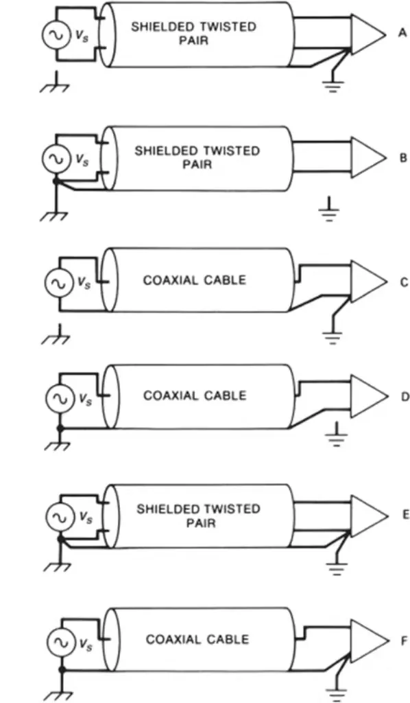
Circuits A–D in the diagram are single-ended grounding cases; whether the shield is grounded at the source or the load depends on the grounding of the source or amplifier (load) circuitry.
Circuit E shows a shielded twisted pair grounded at both ends; if ground potentials differ, loop currents will form in the shield. Circuit F shows a coaxial cable grounded at both ends; because the coax shield is the signal return conductor and the signal is referenced to ground at both ends, the shield should be grounded at both ends, which can also lead to loop currents as in E.
To increase immunity, ground loops can be broken using transformers, optocouplers, or common-mode chokes. A cable shield grounded at one end eliminates power-line frequency noise coupling, but makes the cable act like an efficient antenna at radio frequencies. AM and FM broadcast signals can induce RF currents on the cable shield. If the shield is connected to the circuit ground, those RF currents can enter the equipment and cause interference. Therefore, the correct termination for a shield is to the chassis, not to the circuit ground. The shield should be connected to the chassis at as low an impedance as practical. Any RF noise currents on the shield will then flow harmlessly on the outside surface of the chassis and return to earth via the chassis parasitic capacitance, bypassing sensitive electronics inside the enclosure.
Viewed as an extension of the chassis, the cable shield should be connected with low impedance to the metal enclosure rather than to the circuit ground.
For coaxial cable the shield is the signal return path and therefore must be grounded at both ends for functional reasons; however, for noise mitigation the shield should be terminated to the chassis first. This can be achieved by terminating the cable shield at the chassis and then connecting the circuit ground to the chassis at the same point.
Single-point shield grounding is effective at low frequencies (audio and below) because it prevents mains-frequency currents from traversing the shield and injecting noise into signal circuits. Single-point grounding also eliminates shield ground loops and possible magnetic coupling. As frequency increases, single-point grounding becomes less effective. When the cable length approaches one quarter wavelength, a shield grounded at one end becomes an effective antenna, and it is often necessary to ground the shield at both ends.
Related Reading: EMC Interference: Shielding and Design Principles
2. High-frequency cable shield grounding
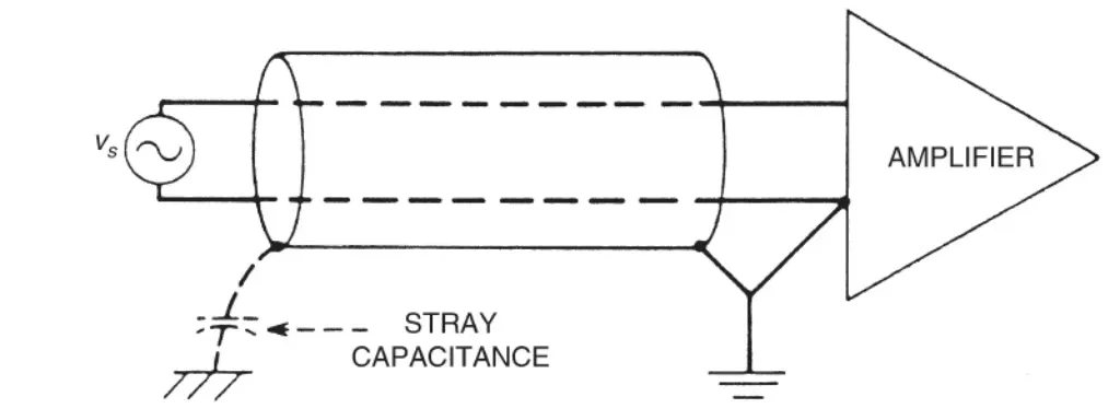
When frequency exceeds about 100 kHz, or when the cable length is greater than one twentieth of a wavelength, the shield should be grounded at both ends (or multiple points). This applies to both multi-conductor and coaxial cables. Another issue at high frequency is that stray capacitances can form ground loops, making it difficult or impossible to isolate the non-terminated end of the shield from ground.
Related Reading: Power Plane EMI Reduction: Shielding Your PCB from Electromagnetic Interference
Therefore, in high-frequency and digital circuits the common practice is to ground cable shields at both ends. Above about 1 MHz, skin effect reduces common-impedance coupling between signal and noise currents in the shield. Skin effect causes noise currents to flow on the outer surface of the shield while signal currents flow on the inner surface. Multipoint grounding also provides magnetic-field shielding above the shield's cutoff frequency.
3. Hybrid cable shield grounding
Single-point grounding is effective at audio and below; multipoint grounding is effective at high frequencies. When a signal contains both low- and high-frequency components, a hybrid approach can be used.
A real capacitor (for example 47 nF) can be used to replace the stray capacitance, forming a combined or hybrid ground. At low frequency the capacitor has high impedance so the shield appears single-ended; at high frequency the capacitor becomes low impedance and the circuit behaves as though the shield is grounded at both ends.
Implementing an effective hybrid shield termination can be difficult because any inductance in series with the capacitor reduces its effectiveness. Ideally the capacitor should be integrated into the connector.
4. Double-layer shielded cable grounding
There are two common uses for double-shielded cable: one is to improve high-frequency shielding, where the two shields may be in contact; the other is to carry both high- and low-frequency signals within the same cable, in which case the two shields must be insulated from each other (often called triaxial cable).
When the two shields are insulated from each other, different termination strategies can be chosen. The outer shield can be grounded at both ends to provide effective high-frequency and magnetic shielding, and to prevent radiation from high-frequency common-mode currents on the cable. The inner shield can be grounded at a single end to avoid ground-loop coupling at low frequencies. In practice the inner shield serves the low-frequency single-point ground and the outer shield serves the high-frequency multipoint ground. The outer shield should be connected to the chassis; the inner shield can be connected to the enclosure or to the circuit ground depending on the application; either approach performs well.
Another termination option for double shields is to ground both shields at one end only, but at opposite ends relative to each other. This arrangement also avoids low-frequency ground loops while allowing the inter-shield capacitance to close the high-frequency return path; it can be effective for long cables.