 ALLPCB


1. Principle of Resonance
Resonance is one of the most common natural phenomena. Many everyday devices and processes operate based on resonance principles. Most matter is composed of molecules that have natural frequencies. When an external energy source approaches a molecule's natural frequency, the molecule more readily absorbs or releases energy, producing amplified vibration. These specific frequencies are called resonance frequencies.
2. Examples of Resonance
Resonance appears throughout nature: acoustic resonance in musical instruments, orbital resonances among some moons of giant planets, resonance of the basilar membrane in animal ears, and electrical circuit resonance.
In the early 19th century, soldiers marching in step caused a bridge in Angers, France to vibrate strongly and collapse. Investigations later identified resonance as the cause.
Machine tools often exhibit slight asymmetries in moving parts that impose periodic forces on other components, causing forced vibration. If the forcing frequency approaches the system's natural frequency, resonance can occur, degrading machining precision and accelerating mechanical fatigue failure.
Examples in electronics include acoustic cavities in string instruments and electrical resonance in radio systems. A radio receiver tunes its antenna to the same frequency as a transmitted wave to produce resonance and receive the signal.
Sound can induce physiological resonance effects. Moderate, regular acoustic energy can influence brain waves, heart rate, and respiration, producing subjective feelings of comfort and relaxation. Acoustic stimulation can modulate cellular and circulatory activity and affect neural excitation levels.
3. Circuit Resonance
Resonance also occurs in electrical circuits, commonly called resonance or LC resonance.
For an LC series circuit, high-frequency signals are significantly attenuated by the inductor, while DC cannot pass through a capacitor. When the input frequency equals the LC series resonant frequency, the series circuit impedance is minimum and current through the LC reaches a maximum. At this frequency, the LC behaves as a large current sink to the signal source.
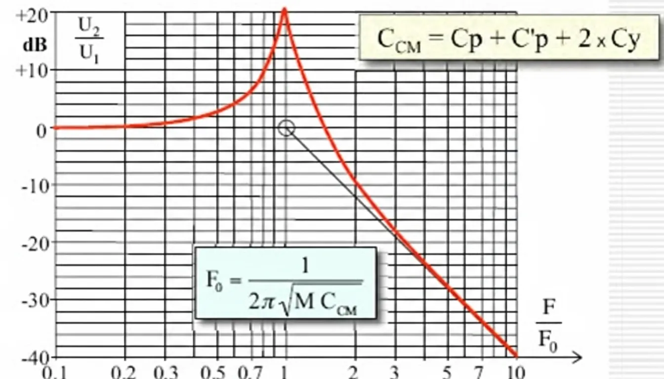
For an LC parallel circuit, due to the impedance characteristics of the inductor and capacitor, higher-frequency signals tend to pass through the capacitor to the output, while lower-frequency signals favor the inductor. The LC loop has maximum impedance at its parallel resonance frequency, preventing signals at that frequency from passing through. At that point, the LC parallel network presents the largest voltage to the power source.
4. Over 80% of EMC Issues Are Related to Resonance
a) Internal resonance in filters
EMC problems in products often manifest as unintended loops in the circuit. These loops inevitably include inductance and capacitance and therefore many resonant points.
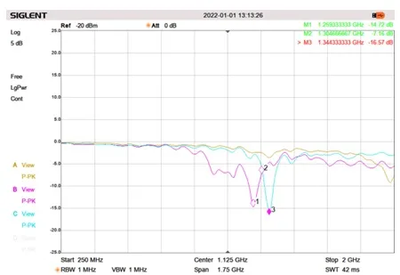
More than 80% of EMC issues are associated with resonance. Resonance complicates EMI analysis and can negate the expected attenuation of filters. The insertion loss plot below shows sharp peaks that correspond to LC resonant points of filter components. At those frequencies, the LC filter not only fails to attenuate but can amplify the original EMI. Therefore, when selecting filter inductance and capacitance values, their resonant points must be far from the target frequencies to be filtered.
In addition to internal resonances formed by filter components, the filter's parameters can resonate with external LC parameters, for example:
- Inductors inside the filter resonating with distributed capacitance outside the filter;
- Capacitors inside the filter resonating with distributed inductance outside the filter;
- Distributed capacitance inside the filter resonating with distributed inductance outside the filter;
- Distributed inductance inside the filter resonating with external inductance, and so on.
This can explain why a filter with excellent standalone insertion loss may not deliver the expected attenuation in a complete product.
b) Resonance can increase EMI emissions
If an internal grounding conductor is too long, near-field noise can couple onto that grounding conductor via distributed capacitance. The conductor's distributed inductance can form a series resonance with the coupling capacitance. At resonance, voltage difference across the grounding conductor can be highest, producing maximum common-mode current on connected system ground conductors and highest radiation.
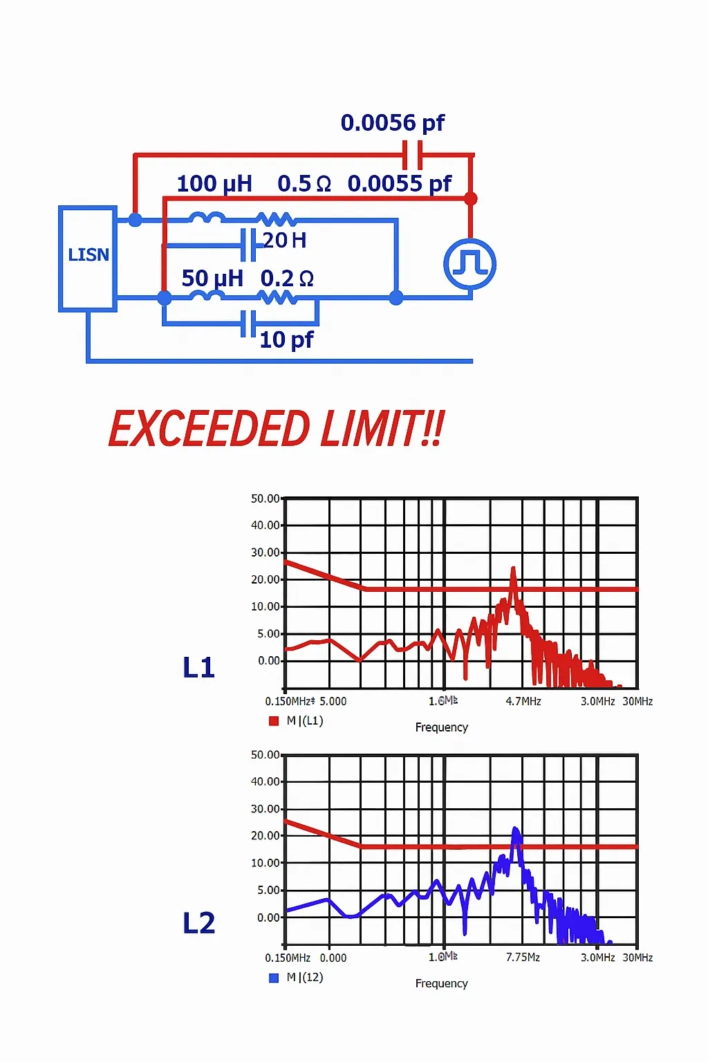
In switching power supplies, high dV/dt on power transistors can capacitively couple into input traces due to PCB layout. The distributed coupling capacitance and the input port inductance can resonate, producing a larger potential difference across the LISN and causing conducted emissions to exceed limits.
c) Resonance can amplify interference
In immunity testing, resonance can produce the strongest disturbance at specific frequencies. During a frequency sweep, an immunity test that applies the same disturbance level may cause failure at only one frequency. This happens when the disturbance frequency coincides with an LC resonance in the system, inducing maximum current. If that induced current flows through the PCB, the PCB experiences maximal interference.
Resonance also reduces test reproducibility. EMC test outcomes depend on layout factors such as cable length, cable height above the reference ground plane, spacing between cables, and EUT placement. These parameters affect distributed values and thus the system's resonant frequencies, causing variability in test results.
In short, products contain many resonant points, most caused by distributed parameters that are difficult to calculate. EMC test bands span from kHz to GHz, and resonant points within this range are hard to avoid. Resonance is therefore a major challenge and can be considered the fundamental nature of many EMC problems.
5. Mitigations for Resonance-Related EMC Issues
Although resonance cannot be completely avoided, several measures can reduce EMC risk:
- Increase values of discrete LC components so that LC resonant points are far from the test band. For example, power filter design may require the filter resonance to be well below 150 kHz to achieve effective attenuation.
- Understand EMC design fundamentals and control distributed parameters, such as reducing ground lead length, shortening capacitor leads, using copper pours between traces, and minimizing signal loop areas. Reducing distributed parameters moves resonant frequencies higher; at higher frequencies the amplitudes of noise harmonics are typically lower, so any resonant amplification has a reduced overall impact.
- Slow the edges of EMI signal sources because edge rate affects harmonic content. Slower edges reduce high-order harmonic amplitude and lower resonance amplitudes at high frequencies. Practical techniques include series resistors and snubber capacitors on switching drive signals.
6. The "Filter Effect" in Practice
A filter that shows excellent insertion loss as a standalone component may not perform as expected once installed in a product. Insertion loss is a performance metric for the filter alone. In a product, the filter's inductance and capacitance can resonate with external inductance or capacitance, causing internal and external components to interact and altering the signal distribution, which can negate the filter's intended effect.
A similar phenomenon occurs in organizations. An individual who performs well alone may not provide proportional value within a team if they have strong interfering interactions with others. Those interactions can continuously absorb organizational resources and degrade overall performance. This organizational analogy is sometimes called the "filter effect" in human resources.


