 ALLPCB


Layout and return current considerations
Layer count, the number of continuous planes, and the chosen board stackup should take EMC concerns into account. Carefully selecting which layer carries which signals helps keep return current close to the corresponding signal traces, and can significantly improve EMC compared with random routing. This careful routing does not increase board cost; it may slightly increase routing time, but is worthwhile given the reduction in EMC issues. Considering return current paths is critical and, in good EMC design, may be the most important concept. EMC design effort should focus on the PCB level rather than shielding; shielding is for last?stage optimization.
Basic diagnostic questions
The first question should always be: where does the signal come from?
The second question should be: how does it get out of the shielded enclosure? Treating these two questions as your basic strategy can reduce time spent in the test lab. Randomly adding ferrite beads, copper tape, or filter capacitors is likely to keep you in the lab longer and increase unnecessary product cost.
Where does the signal originate?
Knowing the signal source lets you trace coupling paths to the outside of the enclosure and decide the best remedy. Clock and data signals are the most likely sources, so identify the system clock frequency and data rate (and their harmonics). Do these frequencies match the problem frequencies? Remember that a 100 Mb/s data rate has a fundamental at 50 MHz and harmonics every 50 MHz.
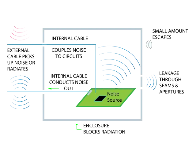
How does the signal get out of the shielded enclosure?
Once you have an idea of the signal source, start investigating how the signal is getting outside the enclosure. A useful first clue is whether the radiation level changes significantly when you move or remove various cables.
Most product enclosures are small and not effective radiators by themselves.
When cables are attached to the product, those cables electrically enlarge the system and become much more effective radiators.
Three ways signals escape the chassis
- Leakage through holes, openings, or gaps
- Coupling from the chassis to cables and unshielded wires
- Leakage at imperfect shielded?cable terminations or shield contacts to the chassis
If signals escape the enclosure for any of the above reasons, moving cables will change the radiated amplitude.


