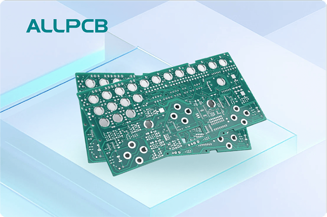
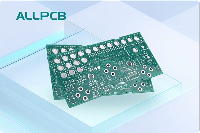
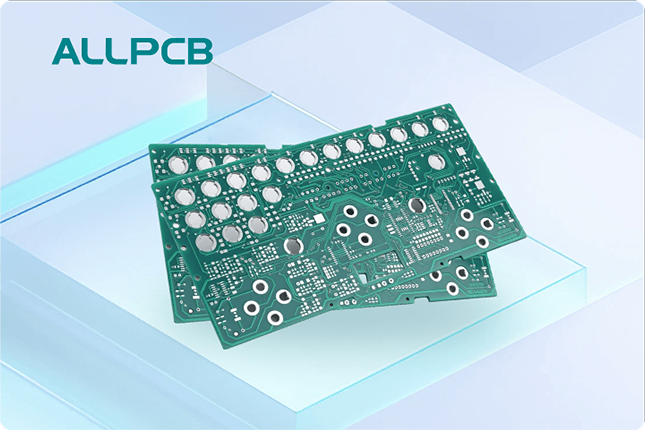
Are you struggling with via issues in your printed circuit board (PCB) designs? If you're looking to fix via DFM challenges, determine which via to use, or learn how to check vias DFM tools can help, you're in the right place. Design for Manufacturability (DFM) software is a powerful solution that identifies and resolves via-related errors before manufacturing, ensuring accuracy and reliability in your PCB projects. In this blog, we'll dive deep into how DFM software transforms via design, prevents costly mistakes, and optimizes your production process.
What Are Vias and Why Do They Cause Issues in PCB Design?
Vias are tiny holes in a PCB that allow electrical connections between different layers of the board. They are essential for routing signals and power in multilayer designs, but they can also be a source of significant problems if not designed correctly. Common via issues include improper sizing, incorrect placement, and failure to meet manufacturing constraints, all of which can lead to signal integrity problems, manufacturing defects, or even complete board failure.
For instance, a via that is too small might not provide a reliable connection, while a via placed too close to other components could cause short circuits or interference. These errors often go unnoticed until the manufacturing stage, where they result in costly rework or delays. This is where DFM software steps in, helping designers catch and fix these issues early in the design process.
Understanding Via Types: Which Via to Use for Your Design?
Choosing the right type of via is critical for ensuring the functionality and manufacturability of your PCB. Let's break down the main types of vias and when to use them:
- Through-Hole Vias: These extend through all layers of the PCB and are the most common and cost-effective option. Use them for simple designs where layer transitions are minimal and space isn’t a major constraint.
- Blind Vias: These connect an outer layer to an inner layer without passing through the entire board. They are ideal for high-density designs where space is limited, as they allow more routing on the surface layers.
- Buried Vias: These are located entirely within the inner layers of the PCB and are not visible on the surface. Use them in complex, multilayer designs to save space and reduce interference, though they are more expensive to manufacture.
- Microvias: These are very small vias, often used in high-density interconnect (HDI) boards. They are perfect for compact designs, such as in smartphones or wearables, but require precise manufacturing capabilities.
Deciding which via to use depends on factors like board complexity, signal speed, and manufacturing cost. For example, in high-speed designs operating at frequencies above 1 GHz, microvias can minimize signal loss (often reducing impedance mismatches by up to 20%) compared to through-hole vias. However, without proper design checks, selecting the wrong via type can lead to manufacturing issues or performance degradation. DFM software analyzes these choices against manufacturing constraints to ensure compatibility and reliability.
Common Via Issues in PCB Design and Their Impact
Via-related errors can derail even the most well-planned PCB projects. Here are some of the most frequent issues designers face:
- Incorrect Via Sizing: If a via’s diameter is too small (e.g., below 0.2 mm for standard processes), it may not be manufacturable or could fail to carry the required current, leading to overheating or breakage. Oversized vias, on the other hand, waste valuable board space.
- Poor Via Placement: Placing vias too close to pads or traces (e.g., less than 0.3 mm spacing) can cause short circuits or soldering issues during assembly. This is especially problematic in high-density designs.
- Signal Integrity Problems: Vias can act as stubs in high-speed designs, causing signal reflections and delays. For instance, a poorly designed via in a 5 GHz signal path could introduce a delay of up to 50 picoseconds, degrading performance.
- Manufacturing Constraints: Not adhering to manufacturer-specific guidelines, such as minimum drill sizes or aspect ratios (e.g., a via depth-to-diameter ratio exceeding 10:1), can result in fabrication failures like incomplete plating or broken drills.
These issues not only affect the performance of the final product but also increase production costs and time. Resolving them after manufacturing is far more expensive than catching them during the design phase, which is why using DFM tools to check vias DFM compliance is so important.
How DFM Software Helps Fix Via Issues
DFM software is a game-changer for PCB designers, offering automated checks and actionable insights to fix via DFM problems before they reach the manufacturing stage. Here's how it works:
1. Automated Via Validation
DFM tools scan your design files to ensure that vias meet manufacturing standards. For example, they check if the via diameter is within the acceptable range (typically 0.2 mm to 0.5 mm for most standard processes) and if the aspect ratio is suitable for reliable drilling and plating. If a via violates these rules, the software flags it and suggests corrections, such as increasing the diameter or adjusting the placement.
2. Signal Integrity Analysis
For high-speed designs, DFM software can simulate how vias affect signal integrity. It identifies potential issues like impedance mismatches or excessive stub lengths and recommends solutions, such as switching to blind vias or adding back-drilling to remove unused via stubs. This can improve signal performance by reducing reflection losses by as much as 15-25% in critical paths.
3. Real-Time Feedback on Placement
DFM tools provide real-time feedback on via placement, ensuring they are not too close to other components or traces. For instance, if a via is placed within 0.2 mm of a solder pad, the software will highlight the risk of short circuits and suggest a safer spacing, typically 0.3 mm or more, depending on the manufacturer’s capabilities.
4. Compatibility with Manufacturing Processes
Every manufacturer has specific capabilities and constraints. DFM software integrates these rules into its analysis, ensuring your via design aligns with the chosen production process. This reduces the likelihood of errors during fabrication, such as incomplete via plating or drill breakage, which can cost hundreds or thousands of dollars in rework for a single batch.
Steps to Check Vias Using DFM Tools
If you're new to using DFM software to check vias DFM compliance, follow these simple steps to ensure your design is error-free:
- Upload Your Design Files: Import your PCB layout files into the DFM tool. Most software supports common formats like Gerber files or native design files from popular CAD tools.
- Define Manufacturing Rules: Input the specific guidelines provided by your manufacturer, such as minimum via size, spacing, or aspect ratio. Some DFM tools already have preloaded rules for standard processes.
- Run the Analysis: Let the software scan your design for via-related issues. This process usually takes just a few minutes, even for complex multilayer boards.
- Review the Report: Examine the detailed report generated by the tool. It will list any via errors, such as undersized drills or improper placements, along with their locations on the board.
- Implement Fixes: Use the software’s recommendations to adjust your design. For example, if a via is too close to a trace, move it to meet the minimum spacing requirement.
- Re-Check Before Submission: Run a final DFM check to confirm all issues are resolved before sending your design for manufacturing.
By following these steps, you can catch and correct via issues early, saving time and money while ensuring a smoother production process.
Benefits of Using DFM Software for Via Design
Integrating DFM software into your PCB design workflow offers numerous advantages, especially when it comes to via accuracy:
- Reduced Design Iterations: By identifying via issues early, DFM tools help you avoid multiple rounds of revisions, cutting down design time by up to 30%.
- Lower Manufacturing Costs: Fixing errors before production prevents costly rework. For example, correcting a via placement issue during design might cost nothing, while fixing it post-manufacturing could cost $500 or more per batch.
- Improved Board Reliability: Proper via design ensures better signal integrity and electrical performance, reducing the risk of field failures by as much as 40% in high-speed applications.
- Faster Time-to-Market: With fewer delays caused by design errors, you can get your product to market quicker, giving you a competitive edge.
Best Practices for Via Design with DFM in Mind
While DFM software is a powerful ally, following best practices during the design phase can further minimize via issues. Here are some tips to keep in mind:
- Start with Manufacturer Guidelines: Always review the via size, spacing, and aspect ratio limits provided by your manufacturing partner before starting your design.
- Minimize Via Count in High-Speed Paths: For signals above 1 GHz, reduce the number of vias in critical paths to avoid signal degradation. Use simulations in DFM tools to test performance.
- Use Standard Sizes: Stick to standard via sizes (e.g., 0.3 mm diameter with a 0.6 mm pad) to ensure compatibility with most manufacturing processes and avoid additional costs.
- Plan Via Placement Early: Position vias away from high-density areas and sensitive components during the initial layout to prevent spacing conflicts.
- Leverage DFM Early and Often: Run DFM checks at multiple stages of your design process, not just at the end, to catch issues as they arise.
Conclusion: Achieve Via Accuracy with DFM Software
Via issues in PCB design can lead to performance problems, manufacturing delays, and increased costs, but they don’t have to be a roadblock. By using DFM software to fix via DFM challenges, determine which via to use, and check vias DFM compliance, you can transform errors into accuracy. These tools provide automated validation, real-time feedback, and manufacturing compatibility checks, ensuring your vias are designed for success from the start.
Whether you're working on a simple two-layer board or a complex HDI design, integrating DFM into your workflow is a smart move. It saves time, reduces costs, and boosts the reliability of your final product. Start leveraging DFM software today to take control of your via design and achieve flawless PCB manufacturing.
 ALLPCB


