 ALLPCB


1. Introduction
As the electromagnetic environment becomes more complex, radiated emission requirements for products are increasing, and more products must consider electromagnetic compatibility issues. Motors are a key component in many products, such as robot vacuum cleaners, vacuum cleaners, electronic door locks, automotive wipers, air-conditioning compressors, and various other motorized products. Motors affect whether overall product emissions meet limits. Common motors include brushed motors and brushless motors. This article analyzes noise sources for brushed DC motors and proposes corresponding mitigation measures, followed by a case study.
2. Brushed Motor Overview
Operating principle:
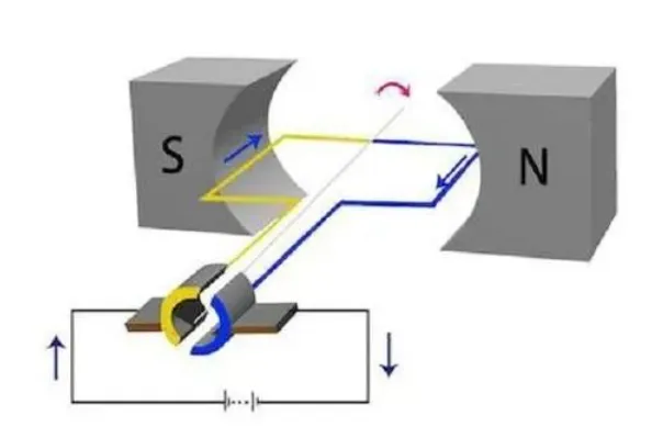
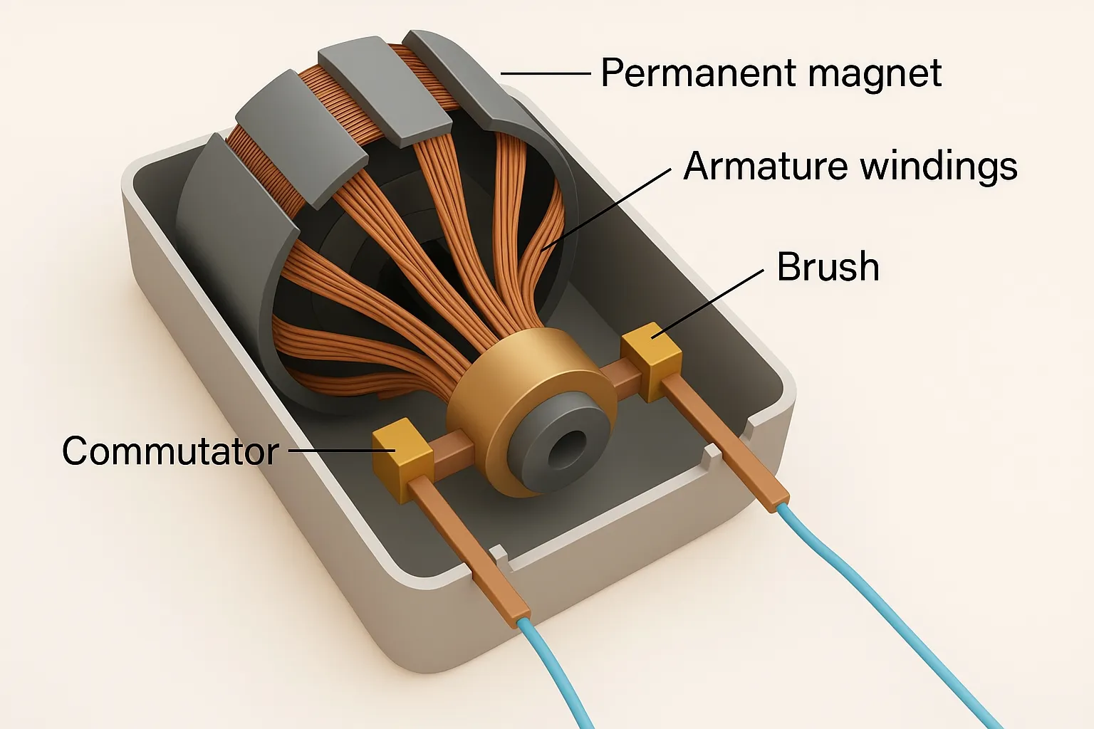
Using the left-hand rule: orient the palm so that magnetic field lines enter the palm (palm facing the N pole, back of the hand facing the S pole), and align the four fingers with the direction of current. The thumb then indicates the force direction on the conductor. In the figure below, S and N are permanent magnets. The coil in the magnetic field experiences a force that causes clockwise rotation. Because of the commutator, after the coil rotates 180°, the direction of current in the coil is still from left to right, so the coil continues rotating clockwise. When there are two, three, or more coils and commutator segments, the device becomes a typical brushed DC motor. The common structure consists of permanent magnets (stator) + coil windings (rotor) + commutator + carbon brushes.
Current path: power supply positive → carbon brush → coil windings → carbon brush → power supply negative.
3. Motor Emission Analysis
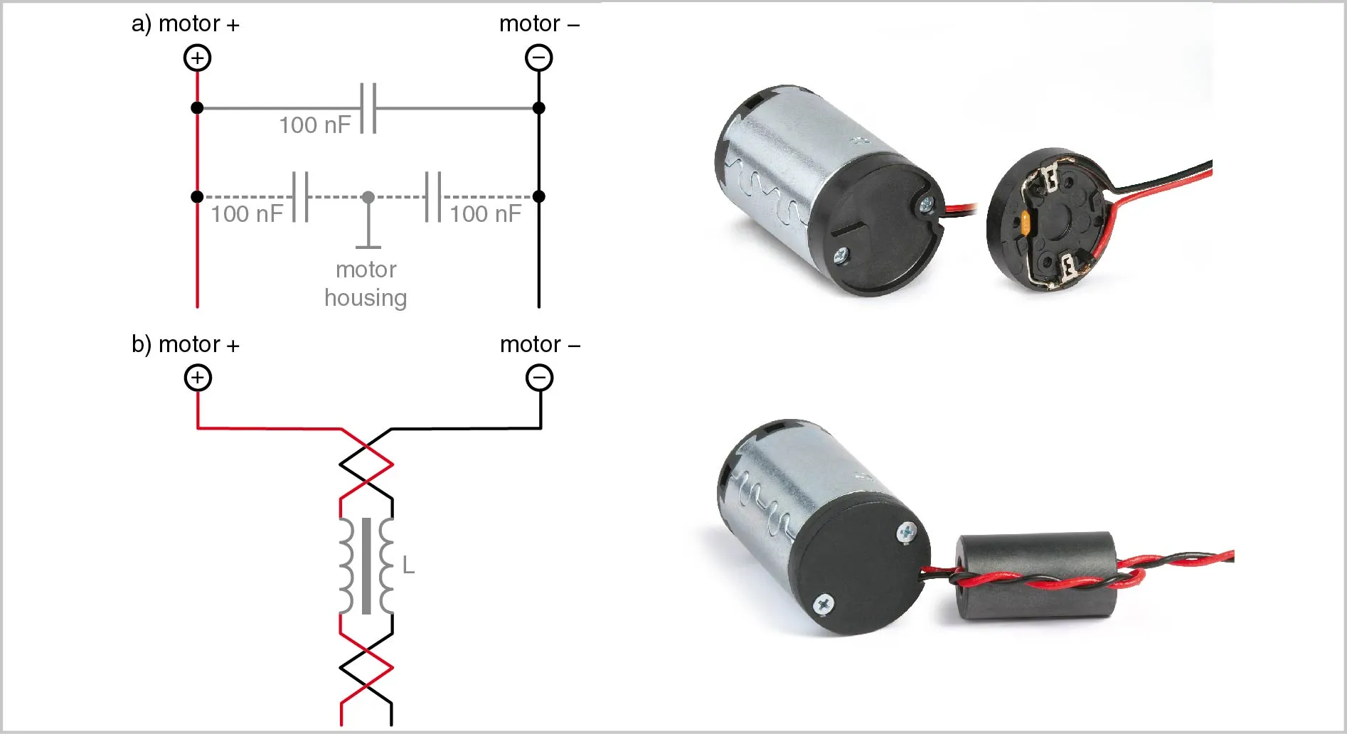
During operation, the commutator continuously rotates, and rapid friction occurs between commutator segments and carbon brushes, causing arcing. Arcing generates high-frequency noise that radiates outward via motor leads and gaps. Metal motor housings can shield and absorb some radiated noise inside the motor, but noise that radiates through the motor leads must be addressed. One approach is to add a small filter board in the motor structure to isolate motor leads from external wiring and reduce motor emissions. Many motors already include some filtering; an example customer motor with an internal small board and its equivalent circuit is shown below.
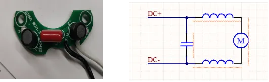
The inductance-plus-capacitance filter shown above resulted in severe radiated emission failures and could not pass testing. That filter only considered differential-mode noise and ignored common-mode noise on the motor leads. Motor emissions generally include both common-mode and differential-mode components.
4. Mitigation Measures
Common filter topologies:
Option 1: Common-mode choke + inductor + capacitor
Advantages: A common-mode choke filters common-mode noise effectively. Capacitors address differential-mode noise. The inductors L1 and L2 located close to the DC motor can effectively suppress commutator arcing.
Disadvantages: The common-mode choke and inductors must be rated for the motor current, and their packages are typically large, so board space must be considered.
Option 2: BDL + ferrite bead
BDL: a multifunction integrated component with good EMI filtering performance.
Advantages: Can suppress both common-mode and differential-mode noise. Due to BDL characteristics, its filtering performance can exceed that of a capacitor or a common-mode choke, with effective frequency coverage up to the GHz range and higher voltage withstand capability.
Disadvantages: The PE connection generally refers to the motor metal housing. The filter board needs a dedicated ground that is connected to the metal housing; the quality of that connection significantly affects filter performance.
5. Example
The following is a motor used in an air pump that was modified for a customer. The implemented solution was BDL + ferrite bead + capacitor. The capacitor was added primarily to increase margin in measured results.
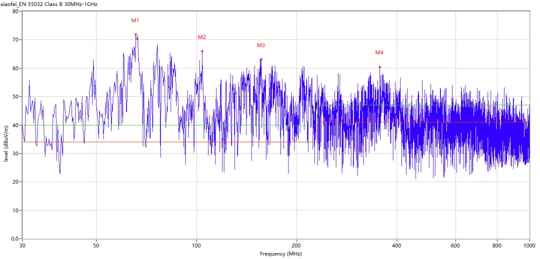
Measured data before modification
Vertical orientation:
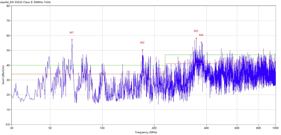
Horizontal orientation:
Measured data after modification
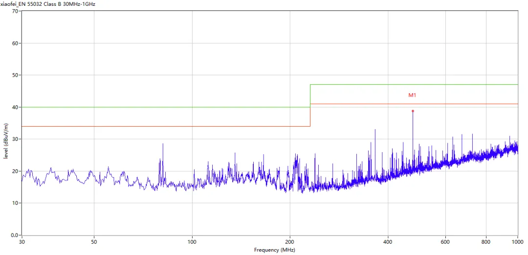
Horizontal orientation:
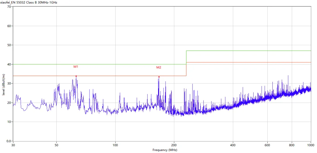
Vertical orientation:
6. Summary
Brushed motor EMC issues relate to motor speed, brush arcing severity, and motor structure. There is no universal solution; mitigation must be tailored to motor characteristics. Both common-mode and differential-mode noise should be considered when designing filters for brushed DC motors.


