Radiated vs. Conducted Emissions
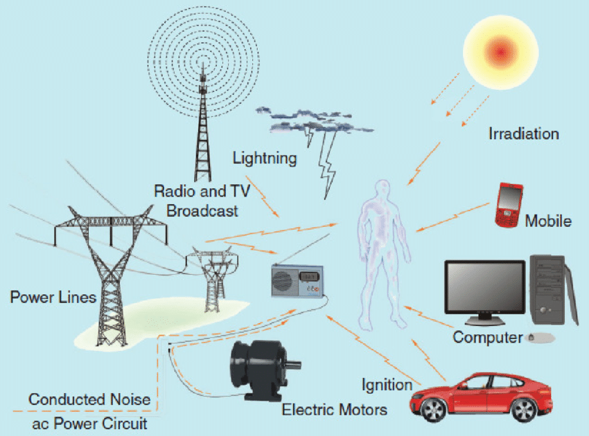
Radiated Emissions (RE) and Conducted Emissions (CE) both measure electromagnetic disturbances, but they describe different transmission paths.
According to the principles of electromagnetic interference (EMI), transmission paths can be divided into two main categories: radiated interference and conducted interference.
When the interference source is far from the equipment under test (EUT), a radiated interference model is used, where the EUT only experiences the effects of the electromagnetic wave.
When the interference source is very close, the source and the EUT are considered part of the same circuit, connected by distributed parameters like capacitance, inductance, and resistance. In this case, circuit analysis methods can be used to determine the interference level.
By convention, if the distance (d) from the interference source to the EUT is much greater than the wavelength (λ), i.e.,  , the device is considered to be in the far-field.
The size of the radiating device must also be considered when determining the near-field/far-field boundary.
For example, in the case of a mobile base station, the far-field boundary is defined as  , where λ is the wavelength of the electromagnetic wave and D is the maximum linear dimension of the antenna.
When the distance between the source and the EUT is very small, a common standard is  , which defines the device as being in the near-field.
The interaction between the source and the EUT occurs through a coupling path formed by (usually distributed) coupling components. The source, the EUT, and the coupling components form a single circuit, which can be analyzed using circuit theory.
Radiated Emissions Testing
RE testing measures the intensity of radiated interference that a device emits into the environment during normal operation. The test site can be a semi-anechoic chamber or an open-area test site (OATS), commonly using the 3-meter or 10-meter method. The test frequency range varies by standard. For example, the Chinese standard GB/T 6113.1 specifies the following frequency bands:
- Band A: 9 to 150 kHz
- Band B: 0.15 to 30 MHz
- Band C: 30 to 300 MHz
- Band D: 300 to 1000 MHz
- Band E: Above 1 GHz
1. Test Equipment
Measuring Receiver
The measuring receiver is a fundamental instrument in EMI testing. Types include quasi-peak, peak, average, and RMS receivers. For some medical device standards (e.g., YY 0505), the receiver must cover a range of 30 MHz to 18 GHz and include Peak (PK), Quasi-Peak (QP), and Average (AV) detectors. Key parameters for a measuring receiver include its 6 dB bandwidth, charge time constant, discharge time constant, mechanical time constant of the critically damped meter, and overload factor.
Antenna
The antenna serves as the receiving device in radiated emissions testing. Different antennas are used for different frequency ranges to cover the full spectrum. Log-periodic antennas are commonly used for RE testing.
2. Test Method
For typical tabletop equipment, the EUT is placed on a non-conductive turntable 80 cm high. The test distance is the horizontal distance from the antenna's reference point to the EUT's geometric center, typically 3 meters. During the test, the turntable rotates from 0 to 360 degrees, while the test antenna's height is varied from 1 to 4 meters (for horizontal polarization) and 2 to 4 meters (for vertical polarization). Measurements are taken in both polarizations to find the maximum disturbance level.
Conducted Emissions Testing
Any non-portable device connects to other equipment via cables, whether for power or signals. This interconnection creates a path for the device's common-mode currents to be conducted to other equipment. This phenomenon is known as conducted interference, or conducted emissions.
Conducted emissions are categorized into two types:
- Power Port CE: Measures interference transmitted from the device's power port onto the AC mains or DC power distribution network. The test frequency range is 150 kHz to 30 MHz.
- Communication Port CE: The test frequency range is the same. This test applies to ports connected to public networks, such as Ethernet or ISDN ports. Signal ports that connect to end-user terminals, like audio/video ports, typically do not require CE testing.
A Line Impedance Stabilization Network (LISN) is used in power port CE testing. It provides a stable impedance and includes a measurement port from which interference conducted along the power line from the EUT is sampled and sent to the receiver for detection.
There are two main test setups:
1. Tabletop Setup
The tabletop EUT is placed 80 cm from the LISN and 40 cm from a vertical ground plane. The EUT and its auxiliary equipment are placed on a non-conductive table 0.8 m above a horizontal ground reference plane. Auxiliary equipment is placed 10 cm from the EUT.
2. Floor-standing Setup
The floor-standing EUT is placed 80 cm from the LISN. The EUT and its auxiliary equipment are placed on a non-conductive support 0.1 m above the horizontal ground reference plane.
 ALLPCB


