 ALLPCB


Overview
The base standard CISPR 16-1-2 defines the specifications, parameters, and calibration methods for current probes, and it is referenced by general standards for information technology equipment, communication equipment, motor vehicles, and military equipment. Current probes are important EMC test instruments and are essential tools for diagnosing EMC issues, particularly for identifying the sources and paths of emissions from cables. This article describes basic methods for using current probes in conducted and radiated testing and diagnosis.
Calibration and Transfer Impedance
Accurate EMI measurements with a current probe require importing the probe's transfer impedance coefficient into the spectrum analyzer or receiver so that measured voltage can be converted to current (voltage / impedance = current). The base standard provides a calibration method for current probes in a 50 Ω system as follows.
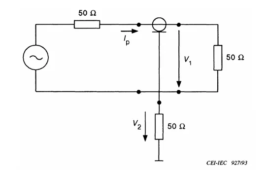
The transfer impedance coefficient of a current probe is obtained from an S21 measurement of insertion loss (V1 - V2, the voltage attenuation). Subtracting 34 dB (the logarithmic conversion for 50 Ω) from the insertion loss yields the transfer impedance coefficient k in dB. During testing, this coefficient converts the receiver voltage to actual current: Ip (dBμA) = V2 (receiver voltage reading in dBμV) + k (dB).
For diagnostic work, a current probe can also directly use the voltage insertion loss coefficient to convert to voltage, which is convenient when using conducted voltage limits.
1. Use of Current Probes for Conducted Testing and Diagnosis
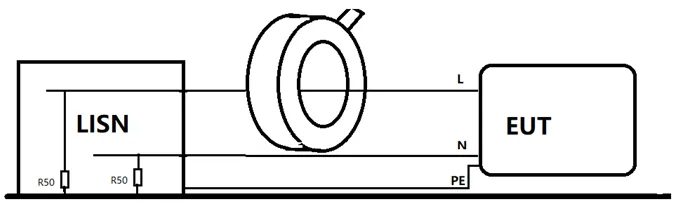
Using current probes for standard conducted testing is a recognized method for network communication equipment, vehicle components, and military-standard devices. When a LISN (Line Impedance Stabilization Network) or artificial mains network is present at the power port (50 Ω or 150 Ω impedance network per CISPR 16-1-2), measurements obtained with a current probe are consistent with LISN test results. Current probe testing is often more convenient, since many ports that cannot be connected to a LISN can still be tested with a current probe. This is important for complex systems and strict EMC requirements. Standard test procedures are defined in the corresponding standards and are not repeated here.
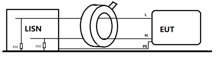
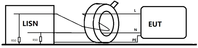
Current probes also provide a fast way to analyze differential-mode and common-mode interference. Under a standard conducted test setup, measuring the spectrum in a few different configurations allows separation of common-mode and differential-mode components, which is useful for diagnosing conducted issues in the laboratory.
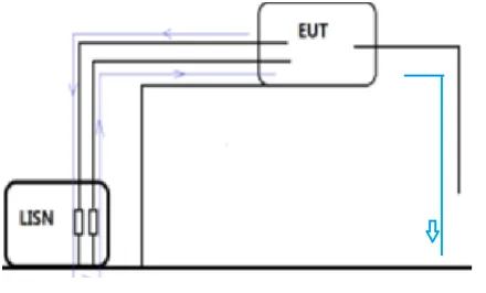
In simple systems, such as equipment with only an input power cable, these methods can quickly identify conducted problems and guide port filter design improvements. In complex systems, high-frequency conducted components (10–30 MHz) often present spectral peaks that are difficult to mitigate by port filtering alone. In such cases, the power port's common-mode current may be a return path for common-mode currents emitted by other cables. Traditional diagnosis relies on experience, cable unplugging, and insertion/removal of clamps. Current probes provide a faster and more direct approach: by measuring common-mode current on non-power cables, engineers can identify offending cables and ports without changing system operating conditions, clarifying the true emission path and verifying the effectiveness of mitigation measures.
During product development, many EMC tests and diagnostics cannot be performed in a formal test chamber (for example, very large or high-power systems, pre-test phases of complex systems, or rapid sub-system evaluations). In these situations, a custom impedance network can be used to filter mains noise and stabilize ground impedance while a current probe is used for quick, flexible conducted measurements.
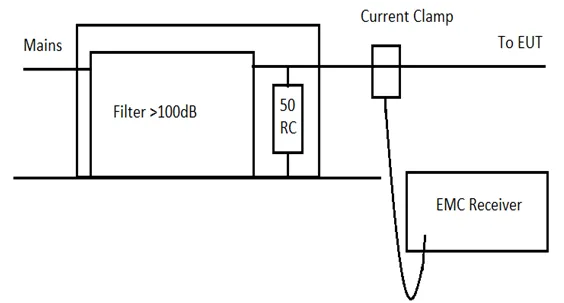
Engineers can set up a conducted test bench in a non-shielded development lab using a standard impedance network and high-performance mains filter, or use an impedance network with filtering to perform measurements in non-standard environments. This reduces EMC risk and testing cost. In urgent field situations, current probes can be used for conducted assessments under arbitrary site conditions, but due to uncertain ground impedance an additional margin should be applied: if a power filter is present at the site but no LISN, evaluate using a 6 dB margin below the limit line; if the device is connected directly to mains without any filter or LISN, use a 10 dB margin below the limit line. Results below the evaluation line can be considered low risk.
Simple Diagnostic Flow for Conducted Issues
- Detect an overlimit conducted frequency using a LISN or current probe.
- Expand the frequency spectrum around the overlimit point to identify spectral details.
- Use a current probe to identify the interfering cable based on the spectrum and determine the path.
- If necessary, use near-field probes to locate the interference source precisely.
- Once source and path are identified, develop mitigation measures.
- Use the current probe or impedance network to compare and verify the effectiveness of each measure quickly.
- Select the optimal solution.
2. Use of Current Probes for Radiated Pre-test and Diagnosis
Principle of Radiated Pre-test with a Current Probe
Antennas are convenient and consistent tools for radiated testing, but they are not optimal for diagnostic analysis. Radiated noncompliance requires an electrically sized radiator, and cables commonly act as such radiators. Measuring currents on cables with a current probe is therefore critical for identifying the primary radiating element. The theoretical basis for current-probe radiated pre-tests comes from classical electromagnetic radiation models.
The left formula shows that for a given antenna, antenna gain and impedance are constant, and the far-field electric field E at distance R depends only on the antenna power P. The right formula shows that antenna radiated power P is a function of displacement current. Combining the two formulas indicates that current I is the primary variable related to the far-field electric field E. Therefore, displacement current on an antenna or cable (common-mode current) has a direct relationship with the far-field electric field, and measuring current on the conductor allows estimation of the radiated field strength.
Limits and Method for Radiated Pre-test
Based on this theory, a current probe can measure common-mode current on cables to perform radiated pre-tests and diagnostics. After theoretical derivation and practical validation, the following common-mode current guideline values are recommended:
- Radiated Class B limit corresponds to a common-mode current limit of 3 μA, which is 10 dBμA or 44 dBμV at a 120 kHz bandwidth.
- Radiated Class A limit corresponds to a common-mode current limit of 10 μA, which is 20 dBμA or 54 dBμV at a 120 kHz bandwidth.
These limits assume many cable emission models approximate a half-wave monopole and that measurements are evaluated in a standard open-area context with the current probe using a voltage coefficient. In practice, for simple cabling the current-probe pre-test results correlate well with chamber antenna measurements. For complex systems with many cables, current-probe assessment provides useful supplemental data. With accumulated experience, this method becomes more accurate and efficient.
The practical value of these limits is that they enable low-cost radiated pre-test evaluations in ordinary open spaces or development labs without access to expensive chambers. This allows EMC tracking and iterative design corrections early in development rather than waiting for final samples and chamber time.
Radiated Diagnosis Flow and Method
When confronted with sudden radiated noncompliance, engineers without current probes often rely on experience and iterative measures such as unplugging cables, adding clamp ferrites, or applying shielding, which can be time-consuming for complex systems. Using a current probe and the limits above enables direct assessment of cables without interrupting system operation, avoiding repeated antenna scans and enabling targeted mitigation.
A typical diagnostic flow using a current probe in a radiated test environment:
- Identify the overlimit radiated frequency with a far-field antenna.
- Expand the spectrum around the overlimit frequency to determine spectral detail.
- Use a current probe and the common-mode current limits to evaluate candidate cables and identify likely radiating cables.
- Use clamp ferrites, shielding, or other path treatments to confirm the radiating and coupled cables and establish the path.
- If necessary, use near-field probes to locate the interference source precisely.
- Develop mitigation measures based on the identified source and path.
- Use the current probe to quickly compare and verify the effects of each mitigation measure.
- Confirm far-field improvement with the antenna and select the optimal solution.
For on-site verification of typical mitigation measures (clamp ferrites, shielded cables, copper foil with grounding, or source-side fixes), the recommended procedure is:
- Clamp the current probe on the cable known to have excessive common-mode current and record the initial spectrum amplitude.
- Apply the mitigation measure (add clamp ferrite near the cable port, replace with shielded cable, wrap with grounded copper foil, or implement source-side corrections) and record the spectrum under the same operating conditions.
- Evaluate effectiveness: clamp ferrites that reduce the affected spectral peak by 3–10 dB are useful; shielding that reduces levels by 30 dB or more is preferable; source-side fixes that remove the spectral peak are optimal.
Any cable-related EMI mitigation should be supported by a measurable reduction in common-mode current on the cable.
EMC engineers need only three tools for conducted and radiated diagnosis: a current probe, a coaxial cable, and a receiver or spectrum analyzer. If the current probe's coefficient for 150 kHz to 1 GHz is imported into the analyzer along with the 150 kHz to 1 GHz radiated and conducted limits (the recommended limits above), both radiated and conducted scans can be performed in a single measurement, which is useful for understanding emission spectra and reducing development cost.
Summary
Current probes offer a convenient, efficient, general-purpose, and low-cost method for conducted and radiated testing and diagnosis. They are valuable tools for EMC engineers during development and troubleshooting and can significantly improve the efficiency of EMC work in engineering practice.


