ALLPCB


What is an antenna?
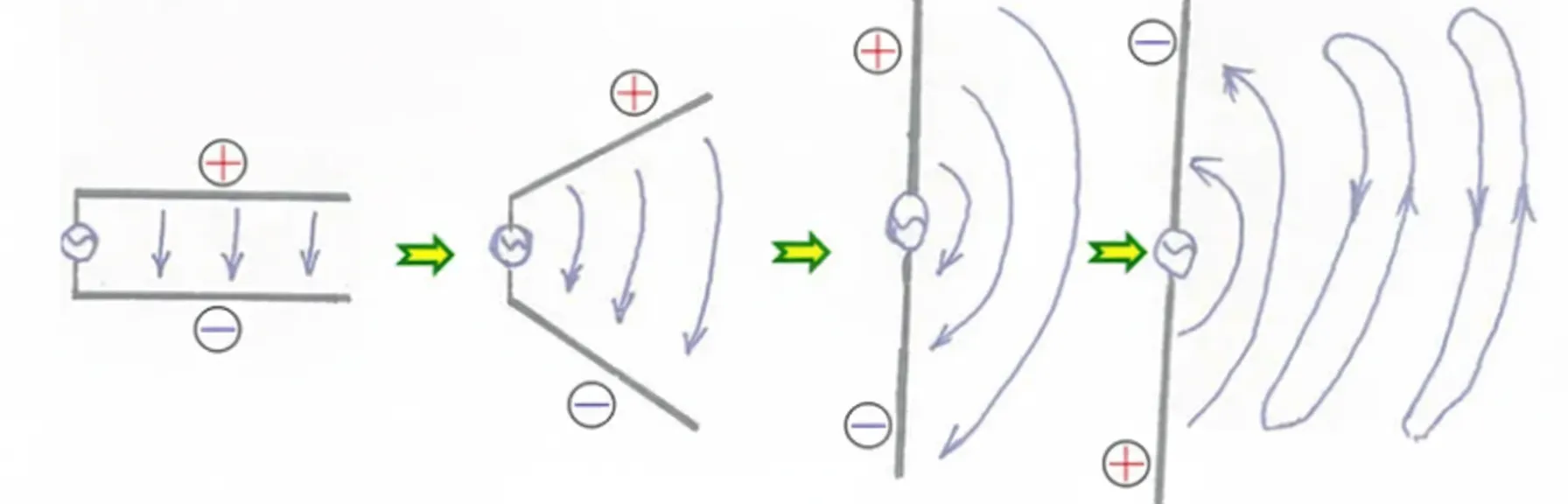
An antenna is a resonant structure exposed to open space that couples guided waves on transmission lines to free-space electromagnetic waves and vice versa. A simple way to visualize a monopole antenna is as a quarter-wavelength transmission line "opened" to free space; when the opened length resonates at a half wavelength, it operates as a standard monopole radiator.
At a basic level, an antenna can be regarded as a conductor whose electrical length is approximately a half wavelength at the operating frequency.
Ceramic antenna: operating principle
In GNSS applications such as GPS, the antenna converts satellite electromagnetic signals into electrical signals the receiver can process. The receiver extracts pseudorandom noise (PRN) codes and navigation data from the received signals to compute position, velocity, and time (PVT). Antennas are reciprocal and can function as both transmitters and receivers.
As a transmitter, an antenna electrode establishes a high-frequency electric field between itself and ground and radiates that field as an electromagnetic wave. As a receiver, the antenna electrode intercepts incoming electromagnetic waves and induces a high-frequency voltage that is passed to the receiver front end for signal processing.
Module design and front-end circuitry
Ceramic antenna modules commonly incorporate low-noise, high-frequency amplifiers in the front end to suppress thermal noise and reduce the loading effect of subsequent amplifier stages. The antenna itself converts the electromagnetic energy from satellites or other transmitters into a current that receiver electronics can process. Antenna geometry and size directly affect the ability to capture weak signals.
Types and manufacturing
Ceramic antennas used in short-range wireless devices such as Bluetooth and in many IoT products include GPS, Bluetooth, and GSM variants. They are available as block ceramic antennas and multilayer ceramic antennas.
Block ceramic antennas are formed by sintering a single ceramic piece at high temperature, after which the conductive antenna pattern is printed on the ceramic surface. Multilayer ceramic antennas are produced by stacking and aligning multiple ceramic layers and co-firing them; conductive traces can be printed on internal layers, enabling smaller overall size and concealed antenna structures.
Material properties and form factor
Ceramic materials typically have a higher dielectric constant than printed circuit board substrates, allowing antenna size reduction for a given resonant frequency. Ceramic dielectrics also can exhibit lower dielectric loss than common PCB materials, making ceramic antennas suitable for low-power wireless modules. Typical ceramic antenna packages approximate 1210 size and generally offer better performance than simple PCB trace antennas.
PCB integration and matching considerations
Ceramic antennas usually provide an ANT connection pad and a ground pad. PCB layouts must maintain a keep-out area around the antenna; in particular, avoid copper pours in the antenna clearance area. Attention must also be paid to balun and impedance matching between the antenna and the transceiver. If a dedicated RF front-end IC is used, verify matching between the IC, any balun network, and the ceramic antenna to avoid degraded performance.
Advantages and limitations
Advantages of ceramic antennas include a compact footprint and relatively good performance for many short-range wireless applications. Limitations include difficulty implementing multi-band operation, which makes them less suitable for applications requiring wideband or multiple cellular bands. They also impose strict PCB clearance requirements and may not be suitable for extremely space-constrained designs.