ALLPCB


Overview
This design note reviews bioelectric potential theory and how to measure ECG using wet or dry electrodes connected to a chest-worn device. It then examines the challenges of conditioning ECG signals to achieve accurate measurements with minimal power. Finally, it proposes a hybrid solution consisting of a biopotential AFE IC, discrete analog filters, and a PMIC.
Introduction
ECG capability is becoming common in health and fitness monitors. If a wearable product lacks ECG, there may be pressure to add the feature quickly. Adding ECG to a wearable can be perceived as costly and time consuming. This article reviews the theory and practice of measuring ECG in chest-worn wearables and outlines a composite approach to speed development and reduce time to integration.
What is Biopotential?
Biopotential measurement requires placing two or more electrodes in contact with the subject's skin to detect the small electrical signals generated by the heart. The signals are then conditioned and sent to a microprocessor for storage, computation, and/or display. Electrocardiography (ECG or EKG) is the time-domain measurement and graphical representation of cardiac-related electrical signals. The R-R interval is the time between successive peak amplitudes of the periodic cardiac signal, also called the R peak (see Figure 2).
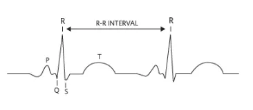
Figure 2. R-R interval in a typical ECG waveform.
ECG and R-R measurements can be used for heart rate monitoring and to assist in diagnosing cardiac conditions such as arrhythmias. These conditions can be intermittent and hard to capture in clinical settings. Wearables enable long-term monitoring outside the clinic, providing more data to support detection and diagnosis. For serious athletes, ECG can provide insight into peak exercise intervals during training.
Measuring with a Chest Strap
Electrodes in contact with the skin, either wet or dry, are used to acquire ECG signals. Clinical electrodes are typically wet and adhere to the body using conductive gel. For chest straps, electrodes are dry. Electrodes are usually two pads made from elastic, conductive materials and connected to a compact, sealed, battery-powered electronics module. The electronics perform ECG signal conditioning and data conversion before wireless communication with a host device, typically via Bluetooth. To keep the sensor light and comfortable, the electronics are often powered by a single coin cell battery. Several design challenges and considerations arise when starting a chest-strap ECG and heart-rate sensor design.
Electrodes and Input Circuit
Electrodes must make good contact with the body to provide sufficiently large and reliable signals for detection. Electrode size and material properties affect signal quality and amplitude. Dry electrodes are more convenient than wet electrodes, but they exhibit very high impedance when first placed on the body. This can attenuate the ECG signal, producing small signals. The "dry start" condition typically lasts briefly until the wearer begins to sweat, reducing impedance and increasing signal levels. To accommodate dry start, the ECG channel input impedance in the analog front end should be very high to minimize attenuation. Also, although clinical ECG uses multiple electrodes on a stationary patient, such an approach is impractical for mobile wearables. The number of electrodes on portable devices should be kept to a minimum, ideally two (single-channel).
Motion Artifacts in the Analog Domain
Several factors degrade signal quality during body movement. For example, clothing impact, chest-strap motion, and electrode movement during running or cycling can introduce interference into the ECG signal. To preserve ECG quality, this motion-induced interference must be suppressed. Motion artifacts typically appear on both electrode pads as common-mode signals, so the analog front end requires the highest possible common-mode rejection ratio (CMRR). Note that heavier sensor electronics are more likely to bounce during use, which increases motion artifacts.
Power Consumption
To maintain comfort and practicality, chest straps must be compact and nonintrusive, minimizing the space for electronics and power, typically a single coin cell battery. This drives the need for extremely low power consumption because any generated heat can cause user discomfort and reduce battery life.
Integrated Solution
Balancing these design constraints is challenging. Achieving the signal quality needed for accurate readings while maintaining reliable, low-power operation in a compact, robust form factor is not trivial. The following sections outline a stepwise approach to adding ECG measurement to a chest-worn wearable.
Step 1: Analog Front End
The AFE required to detect ECG signals includes several building blocks: an input amplifier with low-pass filtering, a PGA, and a high-resolution ADC with digital filtering options. Discrete implementations are impractical in a compact wearable, so an integrated approach is required. When selecting a biopotential ECG AFE for a chest-worn device, important specifications and features include a single input channel with very high series resistance (>500 MΩ) and high CMRR (>100 dB). In addition to meeting ESD (IEC61000-4-2) and EMI filtering requirements, the IC should detect whether its leads are connected (even in sleep mode) or have been detached during normal operation, and it should recover quickly from overvoltage conditions such as defibrillation. These features must be provided at the lowest possible power.
Figure 3 shows a functional block diagram of a fully integrated biopotential ECG AFE used in wearable designs that meet these requirements. One advantage of this device is that it provides an ECG waveform from just a pair of electrodes (single-channel) and also performs heart-rate detection in the same package. Similar ECG AFE ICs do not perform heart-rate detection and instead rely on a microcontroller for computation, which typically consumes an additional 40 μW. The typical current consumption of the described AFE is only 150 μW, nearly 70% lower than comparable devices, allowing coin-cell operation. It complies with the IEC60601-2-47 ECG standard for clinical and fitness applications.
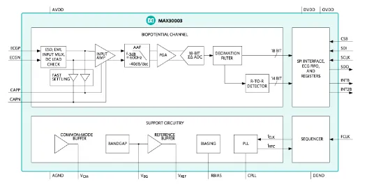
Figure 3. Biopotential AFE IC.
Step 2: Design a Motion-Artifact Bandpass Filter
Before converting the electrode signal to the digital domain, it is preferable to remove or reduce motion artifacts in the analog domain. The primary method is to reduce bandwidth with high-pass and low-pass filters. For the example IC, the single-pole high-pass corner is set by connecting an external capacitor CHPF to the CAPP and CAPN pins, as shown in Figure 4. Values should set the high-pass corner at 5 Hz for high-motion use cases, such as most sports and fitness applications. For clinical applications, the corner can be much lower, often down to 0.5 Hz or even 0.05 Hz, which yields higher-quality diagnostic ECG information when motion is minimal.
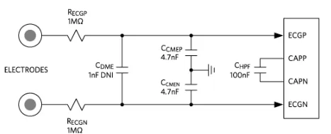
Figure 4. Input analog bandpass filter network.
Figure 5 shows the analog bandpass Bode plot for a chest-strap application.
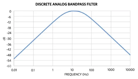
Figure 5. Analog bandpass filter Bode plot for a chest strap.
Using CHPF = 100 nF sets the high-pass corner to about 5 Hz, but for higher-motion requirements this may be raised to 7 Hz (CHPF = 68 nF). The low-pass filter is set by the components left of the CAPP and CAPN pins, namely RECGP, RECGN (1 MΩ), CCMEP, and CCMEN (4.7 nF). This sets the common-mode low-pass corner to 34 Hz, which helps limit shirt or clothing noise during dry start. Limiting the high-end bandwidth is also important to attenuate electrostatic and high-frequency noise. The series resistances RECGP and RECGN should be limited so that the root-sum-square (RSS) of resistor thermal noise and the ECG channel input noise does not exceed the standalone input noise. Differential input capacitor CDME is not used here, but experiments comparing common-mode and differential low-pass filters are recommended because each design has distinct noise sources.
PCB Layout and Component Selection Recommendations
- Use C0G dielectric ceramic capacitors in the signal path where possible to reduce signal distortion; for the ECG path this includes CHPF, CCMEP, CCMEN, and related caps.
- Place discrete components close to the ECG IC and keep traces as short as possible. Maintain length-matched and symmetric traces for differential signals (ECGP/ECGN) to preserve high CMRR.
- Use a single ground plane below the device. Do not split AGND and DGND.
Step 3: Power Options
Depending on the battery type, several options exist to power the wearable. The simplest approach is to use a linear regulator to create a common 1.8 V DC rail from a coin cell, typically between 3.4 V and 2.2 V. However, this approach is not power efficient.
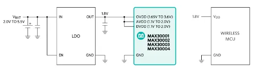
Figure 6. Simple linear LDO power scheme.
While a buck regulator can improve efficiency compared to an LDO, the optimal solution is a PMIC, as shown in Figure 7.
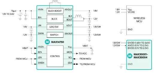
Figure 7. PMIC and 3 V coin cell.
Using a PMIC offers the advantage of providing separate power outputs for the microcontroller, analog front end, and digital interfaces.
Conclusion
This article reviewed bioelectric potential theory and how to measure ECG using wet or dry electrodes connected to a chest-worn device. It considered the challenges of conditioning ECG signals for accurate, low-power measurement. Finally, it proposed a composite solution that combines a biopotential AFE IC, discrete analog filters, and a PMIC, outlining the components needed to integrate ECG into chest-worn health and fitness wearables quickly and with minimal design effort.