 ALLPCB


In the world of educational robotics, creating efficient and compact printed circuit boards (PCBs) is key to building innovative projects. Surface Mount Technology (SMT) offers a powerful solution for designing and assembling PCBs that are smaller, lighter, and more reliable. If you're wondering how to integrate SMT components PCB into your robotics projects, this guide is for you. We'll explore the essentials of SMT, including reflow soldering SMT, component placement SMT, SMT design rules, and the advantages of SMT PCB in educational settings.
This blog will dive deep into each aspect, providing practical tips and actionable advice for students, educators, and hobbyists working on robotics. Whether you're designing a simple robot for a classroom project or a complex system for a competition, SMT can elevate your work. Let's get started!
What is Surface Mount Technology (SMT) and Why Use It in Educational Robotics?
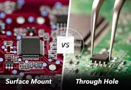
Surface Mount Technology, or SMT, is a method of assembling electronic components directly onto the surface of a PCB. Unlike traditional through-hole technology, where components have leads that go through holes in the board, SMT components are soldered onto pads on the board's surface. This allows for smaller components, tighter layouts, and more efficient designs.
In educational robotics, where space and weight are often critical, SMT shines. Robots built for competitions or classroom demos need compact circuits to fit within tight frames. SMT enables higher component density, meaning you can pack more functionality into a smaller area. Additionally, SMT components are often cheaper in bulk and can improve the performance of high-speed circuits due to shorter connection paths.
Key Benefits of SMT in Educational Robotics PCBs
Understanding the advantages of SMT PCB is crucial for anyone involved in robotics education. Here are some specific benefits tailored to this field:
- Compact Design: SMT components are much smaller than through-hole parts. For instance, an SMT resistor might measure just 1.6mm x 0.8mm (0603 package), allowing you to fit more components on a board as small as 50mm x 50mm for a mini robot.
- Lightweight Construction: Robots often need to meet strict weight limits in competitions. SMT reduces board weight by eliminating bulky leads and using smaller components.
- Cost-Effective for Bulk Production: While initial setup for SMT might require investment, the per-unit cost drops significantly when producing multiple boards for a classroom or team.
- Improved Performance: Shorter connections in SMT reduce signal delay and interference. For robotics projects using high-frequency signals (e.g., 2.4GHz for wireless communication), this can enhance reliability.
- Double-Sided Assembly: SMT allows components to be placed on both sides of the PCB, maximizing space efficiency for complex designs like motor controllers or sensor arrays.
These advantages make SMT an ideal choice for educational robotics, where innovation and efficiency go hand in hand.
Understanding SMT Components for PCB Design in Robotics
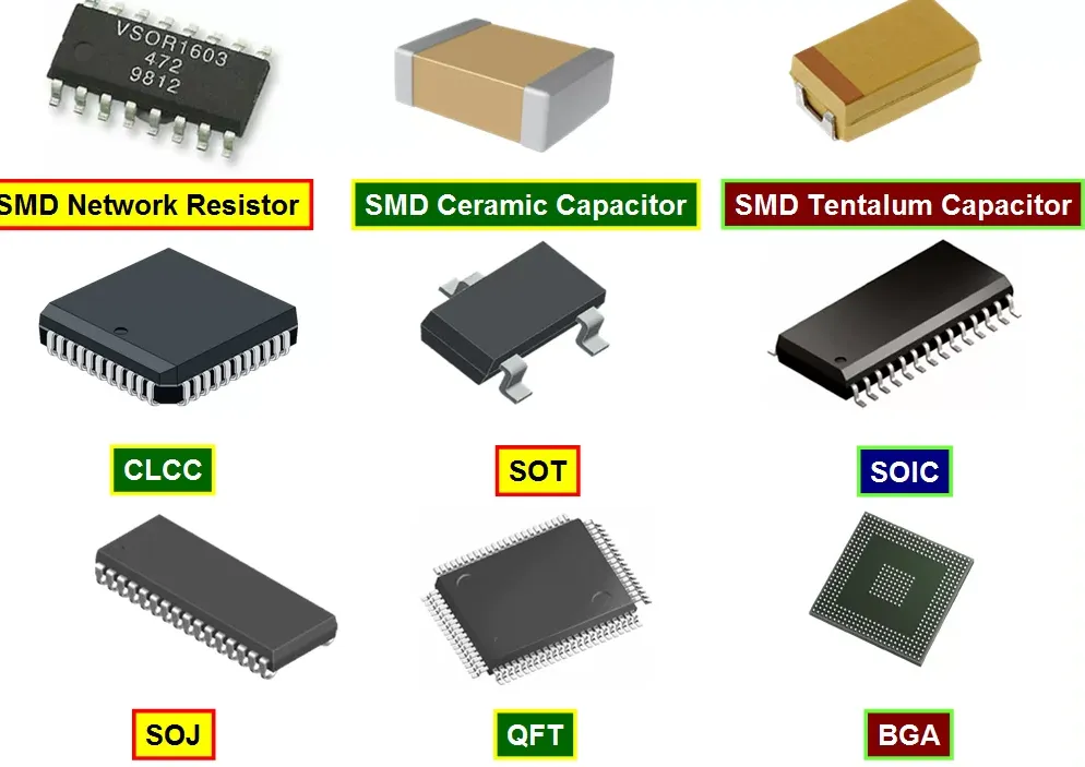
When working with SMT components PCB, it's important to know the types of components you'll encounter and how they fit into robotics projects. Common SMT components include resistors, capacitors, diodes, LEDs, integrated circuits (ICs), and microcontrollers. These come in various package sizes, such as 0402, 0603, or 0805 for passive components, and QFN or BGA for ICs.
For educational robotics, selecting the right components is vital. For example, a microcontroller in a small QFN package (e.g., 5mm x 5mm) can save space on a PCB for a line-following robot, while still providing the processing power needed for sensor input and motor control. However, smaller components can be harder to handle manually, so for beginners, starting with larger SMT packages like 0805 for resistors and capacitors is recommended.
Mastering Component Placement in SMT for Robotics PCBs
Proper component placement SMT is a critical step in designing a functional and reliable PCB for robotics. Poor placement can lead to signal interference, overheating, or manufacturing issues. Here are some practical tips to ensure effective placement:
- Group Related Components: Place components that work together, like a microcontroller and its supporting capacitors, close to each other to minimize signal delay. For instance, decoupling capacitors should be within 2mm of the IC's power pins to reduce noise.
- Consider Heat Dissipation: Power components like motor drivers can generate heat. Place them away from sensitive parts like sensors and ensure there's enough space (at least 5mm) for heat sinks or airflow.
- Optimize for Manufacturing: Align components in the same orientation where possible to simplify automated assembly. Keep at least 0.5mm spacing between components to avoid soldering defects.
- Plan for Accessibility: In educational settings, students may need to test or debug circuits. Place test points or connectors in accessible areas of the board.
By focusing on strategic placement, you can enhance both the performance of your robot and the ease of assembly during production.
Essential SMT Design Rules for Educational Robotics PCBs
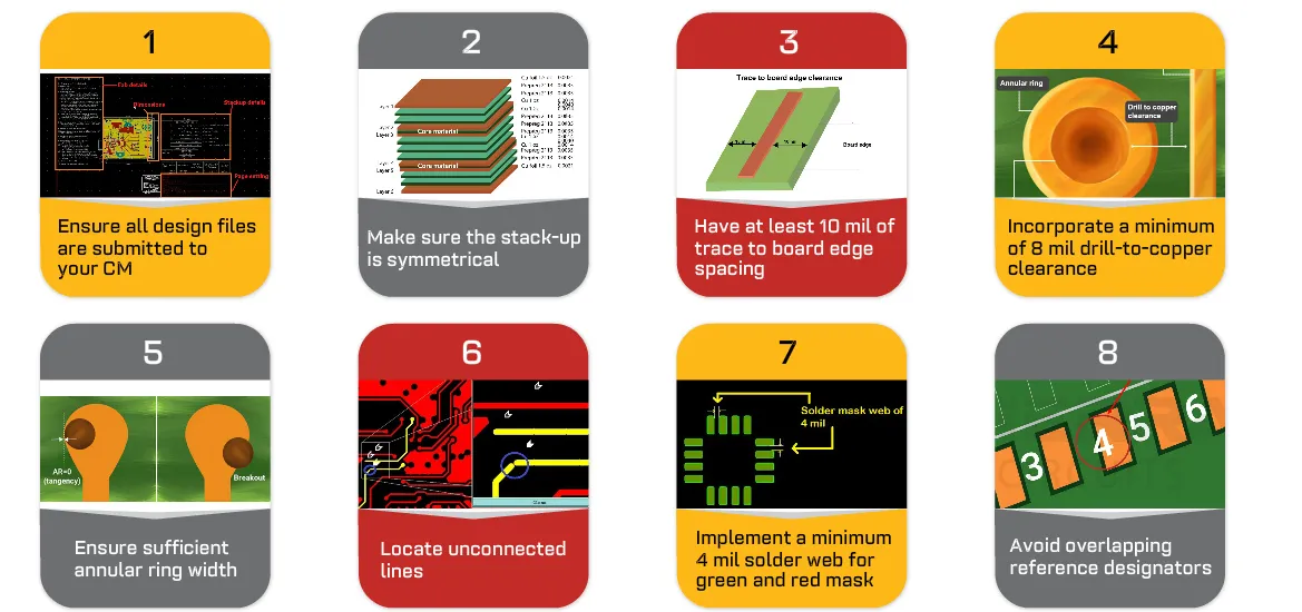
Following SMT design rules ensures that your PCB layout is manufacturable and reliable. These guidelines are especially important in educational robotics, where projects often go through multiple iterations. Here are key rules to keep in mind:
- Pad Size and Spacing: Ensure pad sizes match the component footprint. For a standard 0603 resistor, pads should be approximately 0.9mm x 0.8mm with a spacing of 0.7mm between pads to prevent solder bridging.
- Trace Width and Clearance: Use appropriate trace widths for current-carrying capacity. For example, a 0.2mm trace can handle up to 0.5A, suitable for low-power sensor signals. Maintain at least 0.15mm clearance between traces to avoid short circuits.
- Solder Mask and Silkscreen: Apply solder mask over traces to prevent accidental shorts, and use clear silkscreen labels for component identification—crucial for student projects where debugging is common.
- Via Placement: Avoid placing vias under SMT components as they can interfere with soldering. Keep vias at least 0.3mm away from pads.
- Panelization: If producing multiple boards for a class, design with panelization in mind. Add 2mm spacing between boards for easy separation after assembly.
Adhering to these rules minimizes errors during manufacturing and ensures your robotics PCB performs as intended.
The Role of Reflow Soldering in SMT for Robotics PCBs
Reflow soldering SMT is the most common method for attaching SMT components to a PCB. It involves applying solder paste to the board's pads, placing components, and then heating the assembly in a reflow oven to melt the solder and create strong joints. Here's how this process applies to educational robotics:
- Solder Paste Application: Use a stencil to apply solder paste precisely on pads. For small batches in a classroom, manual application with a syringe can work for larger components (e.g., 0805 packages).
- Component Placement: Automated pick-and-place machines are ideal, but for educational settings, manual placement with tweezers is feasible for prototypes. Ensure components are aligned with pads within 0.1mm for best results.
- Reflow Process: Heat the board in a controlled manner. A typical reflow profile includes a preheat stage (150°C for 60-90 seconds), a soak stage (150-180°C for 60-120 seconds), a reflow stage (peak at 235-250°C for 20-40 seconds), and cooling. This ensures solder melts evenly without damaging components.
- Inspection: After reflow, inspect joints for defects like tombstoning (components lifting on one end) or insufficient solder. Use a magnifying glass or microscope for small parts.
Reflow soldering is efficient for assembling multiple boards, making it a valuable skill for robotics teams producing several units for a project or competition.
Suggested Image Placement: Add an image here of a reflow oven in use or a close-up of a soldered SMT board. ALT Text: "Reflow Soldering SMT for Robotics PCBs"
Challenges of Using SMT in Educational Robotics and How to Overcome Them
While SMT offers many benefits, it also comes with challenges, especially in educational environments. Here's how to address common issues:
- Small Component Handling: SMT parts are tiny and can be difficult to handle without proper tools. Use precision tweezers and magnifying tools to assist students in placing components.
- Equipment Cost: Reflow ovens and pick-and-place machines can be expensive. For small-scale projects, consider using a hot air rework station or even a toaster oven with careful temperature monitoring for reflow soldering.
- Learning Curve: SMT assembly and design require technical knowledge. Incorporate tutorials and hands-on workshops into the curriculum to build student confidence.
- Debugging Difficulty: Soldered SMT components are hard to remove or replace. Equip labs with desoldering tools like hot air guns and provide spare boards for practice.
By anticipating these challenges and preparing solutions, educators can ensure a smooth transition to SMT in robotics projects.
Practical Applications of SMT in Educational Robotics Projects
SMT is already transforming educational robotics in various ways. Here are a few real-world examples of how it can be applied:
- Line-Following Robots: Use SMT to create compact control boards with microcontrollers and infrared sensors, fitting within a 100mm x 100mm footprint for lightweight designs.
- Robotic Arms: SMT allows dense PCB layouts for servo motor drivers, enabling precise control in a small space, ideal for tabletop robotic arm kits.
- Wireless Robots: Incorporate SMT for RF modules operating at 2.4GHz, reducing interference with shorter traces and smaller components for communication reliability.
These applications show how SMT can empower students to build sophisticated robots while learning valuable electronics skills.
Conclusion: Elevating Educational Robotics with SMT
Implementing Surface Mount Technology in educational robotics PCBs opens up a world of possibilities for students and educators. By leveraging SMT components PCB, mastering reflow soldering SMT, optimizing component placement SMT, adhering to SMT design rules, and capitalizing on the advantages of SMT PCB, you can create compact, efficient, and high-performing robots for learning and competition.
While SMT may come with a learning curve and initial challenges, the benefits of smaller designs, improved performance, and cost savings make it a worthwhile investment. With the right tools, training, and mindset, educational institutions can integrate SMT into their robotics programs, preparing students for future careers in electronics and engineering.
Start exploring SMT for your next robotics project today, and watch as your designs reach new levels of innovation and precision!


