 ALLPCB


Wind turbines are at the forefront of renewable energy, converting wind into electricity to power homes and industries. But behind their massive blades and towering structures lies a critical component that ensures their efficiency: heavy copper PCBs. These specialized printed circuit boards are designed to handle high currents and manage thermal challenges, making them essential for wind turbine power electronics. In this blog, we’ll explore how heavy copper PCB design boosts high current PCB for wind turbines, improves PCB power handling, and supports PCB thermal management in these systems.
Whether you’re an engineer designing wind turbine systems or a professional seeking reliable solutions for wind turbine power electronics, this guide will walk you through the benefits, design considerations, and applications of heavy copper PCBs. Let’s dive into the details of why these boards are a game-changer for renewable energy.
What Are Heavy Copper PCBs and Why Do They Matter for Wind Turbines?
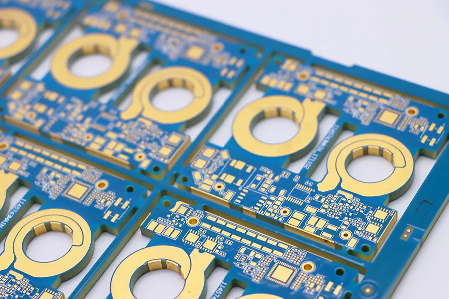
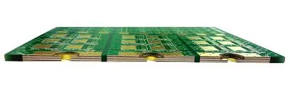
Heavy copper PCBs are printed circuit boards with thicker copper layers, typically ranging from 3 oz/ft2 to 20 oz/ft2 or more, compared to standard PCBs that use 1 oz/ft2 or less. This increased copper thickness allows them to carry higher currents and dissipate heat more effectively, which is crucial for high-power applications like wind turbines.
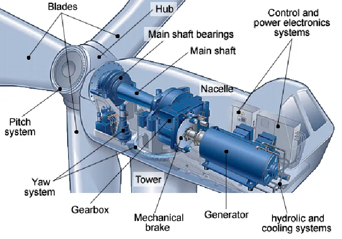
In wind turbine systems, power electronics manage the conversion of variable wind energy into stable electricity. These systems handle currents that can reach hundreds of amperes, generating significant heat in the process. A standard PCB would struggle under such conditions, leading to overheating, performance issues, or even failure. Heavy copper PCBs, on the other hand, are built to withstand these challenges, ensuring reliability and longevity in harsh environments.
Key Benefits of Heavy Copper PCBs in Wind Turbine Power Electronics
Heavy copper PCBs offer several advantages that make them ideal for wind turbine power electronics. Let’s break down the most important benefits:
1. Superior High Current Handling
Wind turbines generate and transmit large amounts of power, often requiring circuits to manage currents exceeding 100 amps. Heavy copper PCBs are designed for high current PCB for wind turbines, as their thicker copper traces reduce electrical resistance and prevent voltage drops. For instance, a 10 oz/ft2 copper layer can handle significantly higher current density compared to a 1 oz/ft2 layer, minimizing the risk of trace burnout.
2. Enhanced PCB Thermal Management
High currents produce heat, and in wind turbines, this heat must be managed to prevent damage to components. Heavy copper PCBs excel in PCB thermal management by acting as a heat sink. The thick copper layers spread heat evenly across the board, reducing hotspots that could degrade performance. In a typical wind turbine inverter, for example, effective thermal dissipation can keep operating temperatures below 85°C, even under full load.
3. Increased Durability in Harsh Conditions
Wind turbines often operate in extreme environments, exposed to temperature fluctuations, humidity, and vibration. Heavy copper PCBs are more robust than standard boards, with stronger mechanical properties that resist cracking and delamination. This durability ensures consistent performance over the turbine’s 20- to 30-year lifespan.
4. Reduced Need for Additional Cooling Systems
Thanks to their heat dissipation capabilities, heavy copper PCBs often reduce the need for external cooling solutions like fans or heat sinks. This not only lowers system costs but also simplifies design and maintenance, which is critical for turbines located in remote or offshore areas.
Design Considerations for Heavy Copper PCB Design in Wind Turbines
Creating an effective heavy copper PCB design for wind turbines requires careful planning. Engineers must balance performance, cost, and manufacturability while meeting the unique demands of high-power systems. Below are key factors to consider:
1. Copper Thickness and Current Capacity
The copper thickness directly impacts the board’s ability to handle current. For wind turbine applications, a thickness of 6 oz/ft2 to 10 oz/ft2 is often used for power conversion circuits. As a rule of thumb, each ounce of copper per square foot can carry approximately 1.2 amps per mil of trace width at a temperature rise of 10°C. Engineers must calculate the expected current load and select the appropriate copper weight to avoid overheating.
2. Trace Width and Spacing
Wider traces are necessary to accommodate high currents without excessive resistance. However, increasing trace width can limit the board’s layout density. Advanced design software can help optimize trace layouts for PCB power handling, ensuring sufficient spacing to prevent arcing or short circuits, especially in high-voltage sections of the turbine’s control system.
3. Thermal Vias and Heat Dissipation
Thermal vias are small holes filled with conductive material that transfer heat from one layer of the PCB to another. In heavy copper designs, thermal vias are critical for PCB thermal management, especially in multi-layer boards. Placing vias near high-power components like MOSFETs or IGBTs in a wind turbine inverter can reduce thermal stress and maintain operating temperatures below critical thresholds, such as 105°C.
4. Material Selection for High Durability
The substrate material of the PCB must withstand the mechanical and thermal stresses of wind turbine operation. FR-4 is a common choice for its cost-effectiveness, but for extreme conditions, high-Tg (glass transition temperature) materials or metal-core PCBs may be better suited. These materials ensure the board remains stable at temperatures up to 150°C or higher.
5. Compliance with Industry Standards
Wind turbine electronics must meet strict standards for safety and reliability, such as IPC-6012 for PCB manufacturing or IEC 61400 for wind energy systems. Adhering to these standards during the heavy copper PCB design process ensures the boards can endure the rigors of long-term operation in renewable energy applications.
Applications of Heavy Copper PCBs in Wind Turbine Systems
Heavy copper PCBs play a vital role in various components of wind turbines, ensuring efficient power management and system reliability. Here are the primary areas where they are used:
1. Power Converters and Inverters
Power converters and inverters transform the variable AC output from the turbine’s generator into stable DC and then back to grid-compatible AC. These systems handle currents in the range of 50 to 500 amps, depending on the turbine’s size (e.g., 2 MW to 5 MW). Heavy copper PCBs provide the necessary PCB power handling to manage these high currents without overheating or efficiency losses.
2. Control Systems
Wind turbines rely on sophisticated control systems to monitor wind speed, blade pitch, and grid conditions. These systems often integrate high-current circuits for actuators and relays, where heavy copper PCBs ensure reliable operation under continuous load.
3. Energy Storage Interfaces
Some wind turbines are paired with energy storage systems to store excess power for later use. The interface between the turbine and battery systems requires robust PCBs to handle high charge and discharge currents. Heavy copper designs are ideal for maintaining stability in these setups.
4. Offshore Wind Turbine Challenges
Offshore wind turbines face additional challenges due to saltwater corrosion and limited access for maintenance. Heavy copper PCBs, with their enhanced durability and thermal performance, are particularly suited for these environments, ensuring long-term reliability without frequent replacements.
Challenges and Solutions in Implementing Heavy Copper PCBs
While heavy copper PCBs offer significant advantages, they also come with challenges that engineers must address during design and manufacturing. Let’s explore these hurdles and how to overcome them:
1. Higher Manufacturing Costs
The thicker copper layers and specialized materials used in heavy copper PCBs increase production costs compared to standard boards. To mitigate this, engineers can optimize the design to use heavy copper only in high-current areas while employing standard copper in low-power sections. This hybrid approach balances cost and performance.
2. Increased Weight and Size
Heavy copper PCBs are heavier and thicker, which can be a concern in space-constrained wind turbine nacelles. Using multi-layer designs with strategic copper placement can help maintain compactness without sacrificing high current PCB for wind turbines capabilities.
3. Complex Fabrication Processes
Manufacturing heavy copper PCBs requires advanced etching and plating techniques to achieve uniform thickness and avoid defects. Partnering with experienced PCB manufacturers ensures high-quality production that meets the stringent demands of wind turbine power electronics.
How Heavy Copper PCBs Contribute to Renewable Energy Goals
The global push for renewable energy has placed wind turbines at the center of sustainable power generation. Heavy copper PCBs support this mission by improving the efficiency and reliability of wind turbine systems. With better PCB thermal management and PCB power handling, these boards reduce energy losses and downtime, maximizing the electricity output of each turbine.
For instance, a 3 MW onshore wind turbine can generate enough power for approximately 2,000 households annually. By using heavy copper PCBs to enhance system performance, the turbine can operate at peak capacity more consistently, contributing to reduced carbon emissions and a cleaner environment.
Future Trends in Heavy Copper PCB Design for Wind Turbines
As wind turbine technology evolves, so does the role of heavy copper PCBs. Emerging trends include the integration of smart sensors for real-time monitoring of thermal and electrical performance, as well as the use of advanced materials like graphene for even better heat dissipation. Additionally, the shift toward larger offshore turbines (up to 15 MW or more) will demand even higher current capacities, pushing the boundaries of heavy copper PCB design.
Conclusion: Powering the Future with Heavy Copper PCBs
Heavy copper PCBs are a cornerstone of modern wind turbine systems, offering unmatched high current PCB for wind turbines capabilities and robust PCB thermal management. From power converters to control systems, these specialized boards ensure that wind energy is harnessed efficiently and reliably, even in the most demanding conditions. By focusing on smart heavy copper PCB design, engineers can overcome challenges like heat buildup and high current loads, paving the way for more powerful and sustainable wind turbine power electronics.


