 ALLPCB


In high-power applications, managing heat in FR-4 PCBs is critical to ensure performance, reliability, and longevity. FR-4, a widely used material in printed circuit boards, has limitations in thermal conductivity, making effective heat dissipation a challenge. So, how can you optimize FR-4 PCB heat dissipation in demanding environments? The answer lies in strategic design techniques like using thermal vias, incorporating heat sinks, and selecting complementary materials to reduce thermal resistance in FR-4. In this comprehensive guide, we’ll explore proven strategies for high-temperature FR-4 PCB designs, diving deep into practical solutions for effective cooling and thermal management.
Understanding FR-4 PCB Thermal Challenges in High-Power Applications
FR-4 is a popular choice for PCBs due to its cost-effectiveness, mechanical strength, and electrical insulation properties. However, its thermal conductivity is relatively low, typically ranging from 0.25 to 0.3 W/m·K, compared to materials like aluminum (around 200 W/m·K) or ceramics (up to 30 W/m·K). This poor FR-4 thermal conductivity becomes a significant issue in high-power applications where components generate substantial heat, such as power supplies, LED lighting, or motor control systems.
Excessive heat can lead to component failure, reduced lifespan, and degraded performance. For instance, operating temperatures above 85°C can accelerate the aging of capacitors and other sensitive components. Therefore, implementing robust FR-4 PCB cooling techniques is essential to maintain safe operating temperatures, often targeting a maximum of 60-70°C on critical areas of the board.
Key Strategies for FR-4 PCB Heat Dissipation
To tackle thermal challenges, engineers can adopt several design and material strategies tailored for high-power applications. Below, we break down the most effective methods to improve heat dissipation and minimize thermal resistance in FR-4.
1. Leveraging Thermal Vias for Enhanced Heat Transfer
One of the most effective ways to manage heat in FR-4 PCBs is by using thermal vias in FR-4. These are small, copper-plated holes that transfer heat from hot components on the top layer to a heat-dissipating layer, such as a ground plane or the bottom side of the board. By creating a direct thermal path, thermal vias can reduce the temperature of critical areas by 10-20°C, depending on their density and placement.
For optimal performance, place thermal vias directly under or near high-power components like power transistors or ICs. A typical via diameter is 0.3-0.5 mm, with a spacing of 1-1.5 mm in a grid pattern. Filling vias with conductive epoxy or copper can further enhance their thermal conductivity, sometimes improving heat transfer by up to 30%.
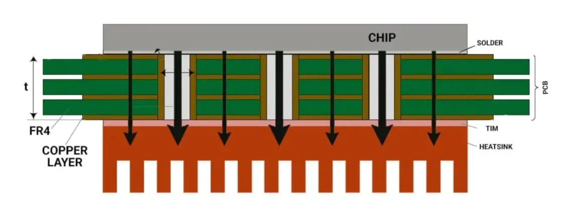
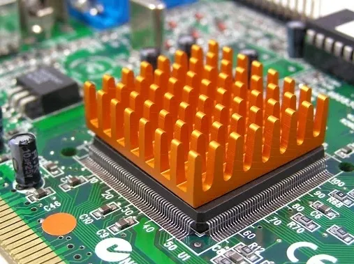
2. Optimizing Heat Sink Design for FR-4 Boards
Attaching heat sinks to high-power components is a proven method to improve heat sink design for FR-4. Heat sinks absorb and dissipate heat into the surrounding air through convection, significantly lowering component temperatures. For FR-4 PCBs, heat sinks are often paired with thermal vias to create a combined heat dissipation path.
When designing a heat sink for an FR-4 board, consider the following:
- Material: Aluminum is a common choice due to its high thermal conductivity (approximately 200 W/m·K) and affordability. For extreme cases, copper heat sinks (around 400 W/m·K) offer even better performance.
- Size and Fin Structure: Larger heat sinks with more surface area (via fins) dissipate heat more effectively. For instance, a heat sink with a fin height of 25 mm can reduce temperatures by 15-25°C compared to a flat plate.
- Thermal Interface Materials (TIMs): Use thermal pads or pastes between the component and heat sink to minimize thermal resistance. High-quality TIMs can have thermal conductivities of 1-5 W/m·K, ensuring efficient heat transfer.
Proper mounting and airflow around the heat sink are also critical. Forced air cooling with fans can enhance heat dissipation by 20-30% compared to natural convection alone.
Related Reading: Thermal Management in PCB Design: Meeting Standards for Heat Dissipation
3. Enhancing PCB Layout for Better Thermal Management
The layout of an FR-4 PCB plays a vital role in thermal management. Poor component placement or inadequate copper planes can trap heat and create hotspots. Here are some layout tips for effective FR-4 PCB heat dissipation:
- Spread Out High-Power Components: Avoid clustering heat-generating components in one area. Distribute them across the board to prevent localized temperature spikes.
- Use Copper Planes: Dedicate large copper areas or ground planes as heat spreaders. Copper has a thermal conductivity of about 400 W/m·K, far superior to FR-4, and can reduce hotspot temperatures by 5-10°C.
- Thicker Copper Layers: Opt for thicker copper (2 oz or 3 oz instead of the standard 1 oz) to improve heat spreading. This can lower thermal resistance by up to 15% in high-current applications.
Additionally, ensure that traces carrying high currents are wide enough to handle the load without excessive heating. For example, a 1 oz copper trace should be at least 50 mils wide for a 5A current to avoid significant temperature rise.

4. Selecting High-Temperature FR-4 Variants
Not all FR-4 materials are created equal. Standard FR-4 has a glass transition temperature (Tg) of around 130-140°C, above which it loses mechanical stability. For high-temperature FR-4 PCB applications, consider using high-Tg FR-4 variants with Tg values of 170-180°C. These materials can withstand continuous operating temperatures of 110-120°C without degrading, making them suitable for power electronics.
High-Tg FR-4 also offers slightly better thermal conductivity (up to 0.4 W/m·K) and improved resistance to thermal cycling stress, extending the board’s lifespan in harsh environments.
5. Implementing Active and Passive Cooling Techniques
Beyond design modifications, FR-4 PCB cooling techniques include both active and passive methods to manage heat:
- Passive Cooling: This relies on natural convection and radiation, using heat sinks and copper planes. It’s cost-effective but limited in high-power scenarios, often achieving temperature reductions of 10-15°C.
- Active Cooling: Fans or liquid cooling systems provide forced convection, significantly improving heat dissipation. A small fan can lower temperatures by 20-30°C, ideal for enclosed systems with limited airflow.
For extreme cases, consider hybrid approaches, such as combining heat sinks with Peltier coolers, though these add complexity and cost.
Related Reading: Thermal Management on Mobile Phone PCBs: Keeping Your Device Cool
Understanding and Reducing Thermal Resistance in FR-4
Thermal resistance in FR-4 refers to the material’s opposition to heat flow, measured in °C/W. A high thermal resistance means more heat buildup, leading to higher operating temperatures. FR-4 typically has a thermal resistance of 50-70 °C/W per square inch, much higher than metal-core PCBs (around 10-20 °C/W).
To reduce thermal resistance, focus on:
- Minimizing Layer Thickness: Thinner FR-4 layers reduce the thermal path, lowering resistance by 5-10% per 0.1 mm reduction in thickness.
- Using Thermal Vias and Copper: As mentioned earlier, these create low-resistance paths for heat to escape.
- Board Size and Orientation: Larger boards and vertical mounting orientations improve natural convection, reducing effective thermal resistance by up to 10%.
By addressing thermal resistance, you can keep component junction temperatures within safe limits, often below 100°C for most ICs, ensuring reliable operation.
Practical Tips for Designing High-Power FR-4 PCBs
Designing for thermal management requires a balance of performance, cost, and manufacturability. Here are actionable tips to guide your process:
- Start thermal analysis early using simulation tools to predict hotspots and temperature rises. Aim for a maximum temperature rise of 20-30°C above ambient under full load.
- Prioritize thermal vias and copper planes in multilayer boards, especially for designs with more than four layers.
- Test prototypes under worst-case conditions (e.g., maximum load at 40°C ambient) to validate thermal performance.
- Consider environmental factors like enclosure design and airflow. Even a small vent can reduce internal temperatures by 5-10°C.
Conclusion: Mastering FR-4 PCB Thermal Management
Effective thermal management is the cornerstone of reliable, high-performance FR-4 PCBs in high-power applications. By leveraging strategies like thermal vias in FR-4, optimizing heat sink design for FR-4, and adopting advanced FR-4 PCB cooling techniques, you can overcome the material’s inherent limitations in FR-4 thermal conductivity. Whether you’re designing for power electronics, LED systems, or industrial controls, these methods ensure your high-temperature FR-4 PCB operates safely and efficiently.
At ALLPCB, we’re committed to supporting engineers with cutting-edge solutions and resources for thermal management. By applying these proven strategies, you can tackle FR-4 PCB heat dissipation challenges and build robust designs that stand the test of time.


