 ALLPCB


Are you looking to create a functional ATM interface using Arduino and a custom PCB? This guide will walk you through the entire process of building a simulated ATM system with a keypad interface, LCD display, and transaction simulation. Whether you're a hobbyist or an engineering student, this project offers a hands-on way to learn about electronics, programming, and PCB design. In this detailed blog, we'll cover everything from the components needed to the step-by-step assembly and coding, ensuring you can replicate this project with ease.
Why Build an ATM Interface with Arduino?
Creating an ATM interface with Arduino is an exciting project that combines hardware and software skills. It simulates real-world banking transactions, making it a great learning tool for understanding user interfaces, input handling, and data processing. By designing a custom PCB for this project, you can also ensure a compact, professional setup tailored to your specific needs. This tutorial targets long-tail keywords like "Arduino ATM," "custom PCB design," "keypad interface," "LCD display," and "transaction simulation" to help you find the right resources and build a successful prototype.
What You'll Need for Your Arduino ATM Project
Before diving into the build, let's gather all the necessary components and tools. Having everything ready will make the process smoother and more efficient. Here's a list of what you'll need:
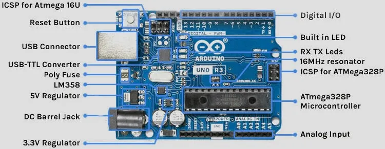
- Arduino Board: A microcontroller like the Arduino Uno or Nano to serve as the brain of your ATM interface.
- Keypad: A 4x4 matrix keypad for user input (PIN entry and menu selection).
- LCD Display: A 16x2 LCD with an I2C module for displaying menus and transaction details.
- Buzzer: For providing audio feedback during transactions or errors.
- Resistors and Capacitors: Various values for circuit stability (e.g., 220-ohm resistors for LEDs or keypad pull-downs).
- LEDs: For status indication (e.g., green for success, red for error).
- Breadboard and Jumper Wires: For prototyping the circuit before PCB design.
- Custom PCB: Designed and manufactured to house all components neatly (more on this later).
- Programming Software: Arduino IDE for coding and uploading the program to your board.
- Soldering Tools: Soldering iron, solder, and flux for assembling the PCB.
Step 1: Understanding the ATM Interface Concept
An ATM interface simulates the basic functionalities of a real ATM, such as entering a PIN, selecting transaction types (withdrawal, balance check, deposit), and displaying results. For this project, the Arduino will handle user inputs from the keypad, display information on the LCD, and simulate transactions by storing and updating a virtual balance in its memory. While this is a simplified version, it mimics core ATM operations and provides a solid foundation for learning.
The custom PCB is crucial as it replaces the messy wiring of a breadboard with a clean, permanent solution. It ensures better signal integrity, reduces noise, and makes the project more durable. For instance, a well-designed PCB can handle impedance matching for faster signal speeds, typically aiming for a 50-ohm impedance for digital signals in microcontroller projects.
Step 2: Designing the Circuit for Your Arduino ATM
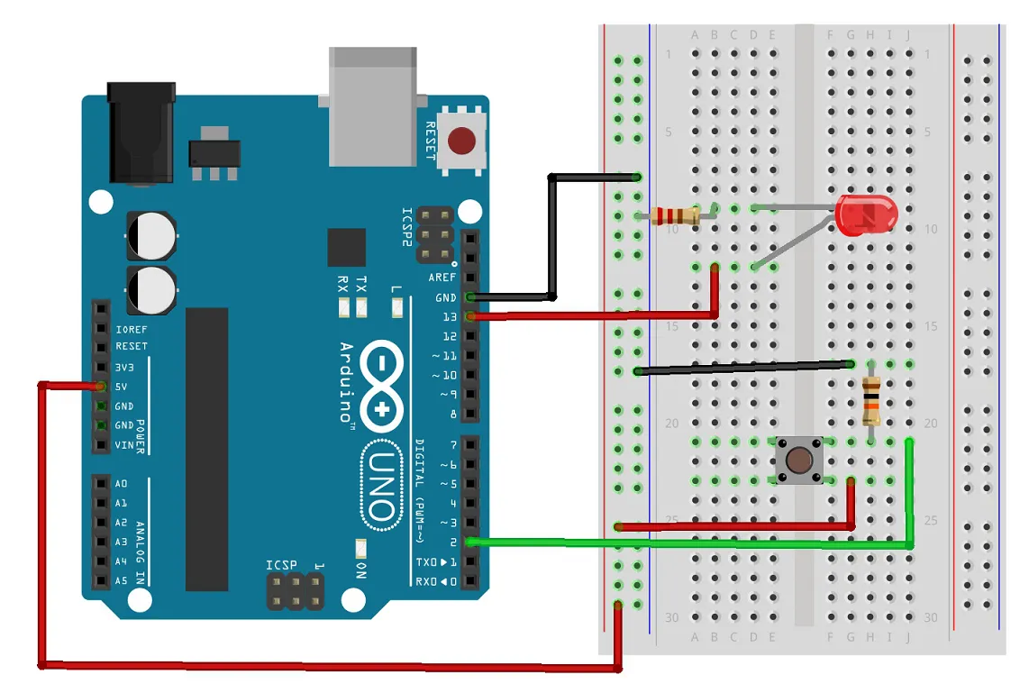
Start by prototyping the circuit on a breadboard to test connections before moving to PCB design. Here's how the components connect:
- Keypad to Arduino: Connect the 4x4 keypad to digital pins (e.g., D2 to D9 on an Arduino Uno). The keypad will use a matrix scanning method to detect key presses.
- LCD Display to Arduino: Use an I2C module with the LCD to save pins. Connect SDA to A4 and SCL to A5 (for Uno), with power to 5V and ground.
- Buzzer and LEDs: Connect the buzzer to a digital pin (e.g., D10) through a 220-ohm resistor for safety. LEDs for status can be connected to other digital pins (e.g., D11 and D12) with similar resistors.
Once the breadboard prototype works, note down the connections and prepare for PCB design. Ensure proper spacing for components and consider adding decoupling capacitors (e.g., 0.1μF) near the Arduino's power pins to filter noise.
Step 3: Custom PCB Design for the ATM Interface
Designing a custom PCB for your Arduino ATM project takes it to the next level. A PCB ensures a compact layout, reduces wiring errors, and improves reliability. Here's how to approach the design:
- Choose a PCB Design Software: Use a free or open-source tool to create your schematic and layout. Popular options include software with community support for beginners.
- Create the Schematic: Draw the circuit based on your breadboard prototype. Include all components (Arduino, keypad, LCD, etc.) and label connections clearly.
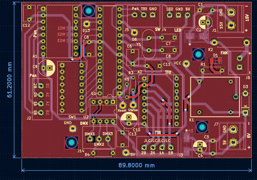
- Layout the PCB: Place components logically, keeping the Arduino near the center for easy access to pins. Route traces with a minimum width of 0.25mm for low-current signals and ensure ground planes for noise reduction.
- Add Mounting Holes: Include holes for screws to secure the PCB in a casing.
- Export and Manufacture: Once the design is ready, export the Gerber files and send them to a trusted PCB fabrication service like ours at ALLPCB for high-quality production.
Designing with a custom PCB also allows for better thermal management. For example, if your ATM interface runs for long periods, copper pours on the PCB can dissipate heat, maintaining a stable operating temperature around 25-30°C under normal conditions.
Step 4: Programming the Arduino for Transaction Simulation
With the hardware ready, it's time to program the Arduino to handle the ATM functionalities. You'll need to install libraries like "Keypad" and "LiquidCrystal_I2C" in the Arduino IDE for the keypad and LCD display. Here's a basic outline of the code structure:
- Initialize Components: Set up the keypad, LCD, and other pins in the setup() function.
- PIN Entry: Prompt the user to enter a 4-digit PIN via the keypad. Compare it with a predefined value (e.g., "1234"). If correct, proceed to the menu; if wrong, sound the buzzer and display an error.
- Transaction Menu: Display options like "1. Check Balance," "2. Withdraw," and "3. Deposit" on the LCD. Use keypad input to select an option.
- Simulate Transactions: For withdrawals, check if the requested amount is less than the virtual balance (start with a balance of 1000 units). Update the balance accordingly and show results on the LCD.
Here's a snippet of pseudo-code for the PIN entry:
if (keypad.getKey() != NO_KEY) { enteredPIN += key; if (enteredPIN.length() == 4) { if (enteredPIN == correctPIN) { lcd.print("Access Granted"); } else { lcd.print("Access Denied"); tone(buzzerPin, 1000, 200); } } }
This code ensures secure access and provides feedback, simulating a real ATM experience. Adjust timing delays (e.g., 200ms for buzzer tone) to match user interaction needs.
Step 5: Assembling and Testing the ATM Interface
After receiving your custom PCB from a reliable fabrication service like ALLPCB, it's time to assemble the components. Follow these steps:
- Solder Components: Place and solder each component onto the PCB according to your design. Start with smaller components like resistors, then move to larger ones like the Arduino socket.
- Double-Check Connections: Use a multimeter to ensure there are no short circuits and that all traces are connected as intended (e.g., check for 5V at power pins).
- Upload Code: Connect the Arduino to your computer and upload the finalized code.
- Test the System: Power up the system and test each feature—PIN entry, menu navigation, and transaction simulation. Ensure the LCD displays text clearly and the keypad responds accurately.
If issues arise, check for loose connections or coding errors. For instance, if the LCD shows garbled text, verify the I2C address (commonly 0x27) in your code matches the module's address.
Suggested Image Placement: Add a photo of the assembled PCB with components soldered in place. ALT Text: "Assembled Custom PCB for Arduino ATM Interface."
Step 6: Adding a Professional Touch with Enclosure
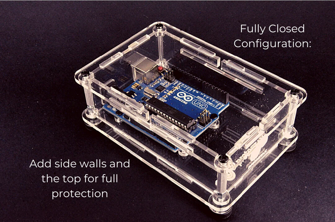
To make your Arduino ATM interface look like a real device, consider designing a simple enclosure. You can use 3D printing or laser-cut acrylic to create a casing that houses the PCB, keypad, and LCD. Ensure openings for the keypad buttons and LCD screen, and add slots for power cables. This not only protects the electronics but also enhances the project's aesthetic appeal.
Troubleshooting Common Issues
Even with careful planning, you might face challenges. Here are solutions to common problems:
- Keypad Not Responding: Check pin connections and ensure the keypad library is correctly installed. Test with a simple sketch to print key presses to the Serial Monitor.
- LCD Not Displaying: Verify power connections and I2C address. Adjust the contrast using the potentiometer on the I2C module.
- Transaction Errors: Debug the code by adding Serial.print statements to track variable values like balance or entered PIN.
By addressing these issues systematically, you can ensure your project runs smoothly.
Why Choose ALLPCB for Your Custom PCB Needs?
When it comes to manufacturing your custom PCB for projects like this Arduino ATM interface, quality and reliability are key. At ALLPCB, we offer high-precision PCB fabrication with fast turnaround times, ensuring your design is brought to life exactly as envisioned. Our services support various layer counts, materials, and finishes, catering to both prototype and production needs. Plus, our user-friendly platform makes uploading designs and getting quotes a breeze, saving you time for innovation.
Conclusion: Take Your Arduino ATM Project Further
Building an ATM interface with Arduino and a custom PCB is a rewarding project that sharpens your skills in electronics, programming, and design. From wiring a keypad interface to simulating transactions on an LCD display, this guide has covered every step to help you succeed. With a custom PCB, your project gains durability and a professional look, making it stand out.
Whether you're using this for a school project or just to explore Arduino capabilities, the possibilities are endless. You can expand this system by adding features like RFID card reading for authentication or connecting to a database for real transaction logging. Start building today, and let your creativity lead the way with support from ALLPCB for all your PCB fabrication needs.


