 ALLPCB


Designing a 16-layer PCB stackup can be a complex task, but with the right layer arrangement, you can ensure optimal signal integrity, effective power distribution, and minimal electromagnetic interference (EMI). In this guide, we’ll dive deep into the essentials of a 16-layer PCB stackup, covering signal layer placement, ground plane distribution, and power plane design. Whether you’re an experienced engineer or new to multilayer PCB design, this comprehensive resource will help you build a robust and efficient board for high-speed and high-density applications.
What Is a 16-Layer PCB Stackup and Why Does It Matter?
A 16-layer PCB stackup refers to the arrangement of conductive copper layers and insulating dielectric materials in a printed circuit board with 16 layers. These layers include signal layers for routing traces, ground planes for shielding and return paths, and power planes for stable voltage distribution. The stackup design directly impacts signal integrity, power delivery, thermal management, and EMI control, making it a critical aspect of PCB design for complex electronics like servers, telecommunications equipment, and advanced medical devices.
Proper layer arrangement in a 16-layer PCB ensures that high-speed signals are protected from interference, power delivery is consistent, and the board can handle dense component layouts. Let’s explore how to structure these layers effectively.
Key Principles of 16-Layer PCB Stackup Design
Before diving into a specific layer arrangement, it’s important to understand the guiding principles behind a well-designed 16-layer PCB stackup. These principles focus on balancing signal integrity, power distribution, and manufacturability:
- Signal Integrity: High-speed signals need controlled impedance (typically 50 ohms for single-ended signals or 100 ohms for differential pairs) and minimal crosstalk. This requires careful placement of signal layers next to reference planes (ground or power).
- EMI Control: Ground planes act as shields, reducing noise and preventing interference between signal layers. Distributing ground planes strategically is key.
- Power Distribution: Power planes should be placed to minimize voltage drops and ensure stable current delivery, often using multiple planes for different voltage levels (e.g., 3.3V, 5V).
- Thermal Management: A balanced stackup helps distribute heat evenly across the board, preventing hotspots in dense designs.
- Manufacturability: Symmetrical stackups prevent warping during fabrication, and proper dielectric thickness (e.g., 0.1 mm to 0.2 mm between layers) ensures consistent performance.
With these principles in mind, let’s move on to a practical 16-layer PCB layer arrangement.
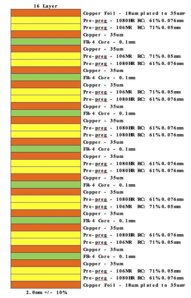
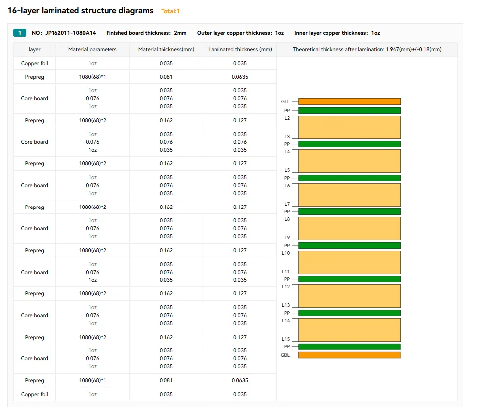
Recommended 16-Layer PCB Stackup Arrangement
A typical 16-layer PCB stackup prioritizes signal layers near the top and bottom for easy access during routing, while internal layers are dedicated to power and ground planes for shielding and stability. Below is a common configuration for a high-speed design, though it can be adjusted based on specific project needs:
- Layer 1: Top Signal (High-Speed Signals)
- Layer 2: Ground Plane
- Layer 3: Signal Layer (High-Speed)
- Layer 4: Ground Plane
- Layer 5: Power Plane (e.g., 3.3V)
- Layer 6: Signal Layer (Mixed Signals)
- Layer 7: Ground Plane
- Layer 8: Signal Layer (Mixed Signals)
- Layer 9: Signal Layer (Mixed Signals)
- Layer 10: Ground Plane
- Layer 11: Signal Layer (Mixed Signals)
- Layer 12: Power Plane (e.g., 5V)
- Layer 13: Ground Plane
- Layer 14: Signal Layer (High-Speed)
- Layer 15: Ground Plane
- Layer 16: Bottom Signal (High-Speed Signals)
This arrangement places high-speed signal layers (Layers 1, 3, 14, and 16) near ground planes for controlled impedance and shielding. Power planes are positioned internally to distribute voltage evenly, while multiple ground planes reduce noise and provide return paths for signals. The middle layers (6, 8, 9, 11) handle mixed or lower-speed signals, ensuring flexibility in routing dense designs.
Signal Layer Placement in a 16-Layer PCB
Signal layer placement is crucial for maintaining signal integrity, especially in high-speed designs where data rates can exceed 10 Gbps. Here are the key considerations for arranging signal layers in a 16-layer PCB stackup:
- Place High-Speed Signals Near Ground Planes: As seen in the stackup above, high-speed signal layers (1, 3, 14, 16) are adjacent to ground planes. This minimizes loop inductance and ensures a consistent return path, reducing EMI. For example, a 50-ohm trace on Layer 1 can maintain impedance with a 0.1 mm dielectric separation from Layer 2 (ground).
- Separate High-Speed and Low-Speed Signals: High-speed signals should be isolated from slower analog or digital signals to avoid crosstalk. In the suggested stackup, middle layers (6, 8, 9, 11) handle mixed or lower-speed signals, while outer layers focus on critical high-speed traces.
- Use Stripline or Microstrip Configurations: Outer signal layers (1 and 16) are ideal for microstrip routing (signal over a single ground plane), while internal signal layers (3 and 14) use stripline routing (signal between two reference planes) for better shielding.
By following these guidelines, you can ensure that your signal layers support high-speed performance without interference or signal degradation.
Ground Plane Distribution for Noise Reduction
Ground planes play a vital role in a 16-layer PCB stackup by providing a low-impedance return path for signals and shielding against EMI. Here’s how to distribute ground planes effectively:
- Place Ground Planes Near Signal Layers: In the recommended stackup, ground planes (Layers 2, 4, 7, 10, 13, 15) are positioned next to signal layers to minimize noise. This ensures that every signal layer has a nearby reference plane for stable impedance.
- Use Multiple Ground Planes: With six ground planes in the 16-layer design, you can dedicate specific planes to different circuit sections (e.g., digital and analog grounds) to prevent noise coupling. If a single ground is sufficient, connect all planes with vias for a unified reference.
- Avoid Splitting Ground Planes Unless Necessary: Splitting a ground plane under a signal trace can disrupt the return path, increasing EMI. If splitting is required for mixed-signal designs, ensure signals do not cross the split.
Effective ground plane distribution is the backbone of a low-noise design, ensuring that your 16-layer PCB performs reliably even in demanding applications.
Power Plane Design for Stable Voltage Delivery
Power planes in a 16-layer PCB stackup are essential for delivering stable voltage to components, especially in designs with multiple voltage levels. Here’s how to design and position power planes:
- Dedicate Layers to Specific Voltages: In the suggested stackup, Layer 5 handles 3.3V and Layer 12 handles 5V. If your design requires additional voltages (e.g., 1.8V), you can allocate another internal layer or split a power plane with careful planning.
- Place Power Planes Near Ground Planes: Positioning power planes next to ground planes (e.g., Layer 5 next to Layer 4) creates a natural capacitance, reducing noise and stabilizing voltage. A thin dielectric (e.g., 0.05 mm) between power and ground enhances this effect.
- Use Decoupling Capacitors: Place decoupling capacitors close to power pins of ICs, connecting them to power and ground planes with short vias. This minimizes voltage fluctuations during high-frequency switching.
- Minimize Power Plane Splits: Similar to ground planes, avoid splitting power planes unless absolutely necessary, as it can lead to uneven current distribution.
Well-designed power planes ensure that your board delivers consistent power, even under heavy load conditions, supporting reliable operation of complex circuits.
Dielectric Material and Thickness Considerations
The dielectric material and thickness between layers in a 16-layer PCB stackup affect impedance, signal speed, and manufacturability. Here are some key points to consider:
- Material Selection: Common materials like FR-4 (dielectric constant of 4.2-4.5) are cost-effective for standard designs. For high-speed applications, low-loss materials like Rogers 4350B (dielectric constant of 3.48) reduce signal attenuation.
- Dielectric Thickness: For controlled impedance, maintain consistent dielectric thickness between signal and reference layers (e.g., 0.1 mm for 50-ohm traces). Thicker dielectrics (e.g., 0.2 mm) may be used between power and ground for higher capacitance.
- Symmetry: Ensure the stackup is symmetrical to avoid warping. For example, if the top half has a certain layer order, mirror it in the bottom half as closely as possible.
Choosing the right dielectric properties and maintaining uniform thickness ensures that your 16-layer PCB meets performance and manufacturing requirements.
Challenges and Solutions in 16-Layer PCB Stackup Design
Designing a 16-layer PCB stackup comes with challenges, especially for high-density and high-speed applications. Below are common issues and practical solutions:
- Challenge: Signal Crosstalk
Solution: Increase spacing between signal traces (e.g., maintain 3x the trace width) and ensure signal layers are separated by ground planes for shielding. - Challenge: Thermal Hotspots
Solution: Distribute power-hungry components evenly and use thermal vias to transfer heat to inner ground planes. - Challenge: Manufacturing Complexity
Solution: Work closely with your fabrication partner to verify stackup feasibility, ensuring layer thicknesses and materials are within their capabilities. - Challenge: Cost Constraints
Solution: Optimize the number of signal layers and avoid over-specifying materials. Use standard FR-4 where high-speed performance isn’t critical.
Addressing these challenges early in the design phase can save time and resources, leading to a more successful PCB project.
Applications of 16-Layer PCB Stackups
A 16-layer PCB stackup is ideal for applications requiring high density, high speed, and robust power delivery. Some common uses include:
- Telecommunications: High-speed data transfer equipment like routers and switches benefit from multiple signal layers and controlled impedance.
- Computing: Servers and motherboards use 16-layer designs to support dense component layouts and multiple voltage rails.
- Medical Devices: Advanced imaging systems require low-noise designs, achieved with strategic ground plane distribution.
- Aerospace: Ruggedized electronics in satellites and avionics rely on multilayer stackups for reliability under extreme conditions.
These applications highlight the versatility and importance of a well-designed 16-layer PCB stackup in modern electronics.
Tips for Optimizing Your 16-Layer PCB Stackup
To wrap up, here are some actionable tips to refine your 16-layer PCB layer arrangement:
- Simulate your stackup using design software to verify impedance and signal integrity before fabrication.
- Plan via placement early, using blind and buried vias to connect internal layers without crowding outer layers.
- Balance the number of signal, ground, and power layers based on your design’s specific needs—don’t over-allocate layers unnecessarily.
- Keep dielectric thicknesses uniform to maintain consistent impedance across signal layers.
- Collaborate with your manufacturer to ensure the stackup aligns with their process capabilities, avoiding costly redesigns.
Conclusion
Designing a 16-layer PCB stackup is a balancing act between signal integrity, power distribution, and manufacturability. By following the layer arrangement guidelines outlined in this guide, including strategic signal layer placement, effective ground plane distribution, and thoughtful power plane design, you can create a board that meets the demands of high-speed and high-density applications. Remember to consider dielectric materials, address potential challenges, and optimize your design for both performance and cost.
With this comprehensive approach to 16-layer PCB stackup design, you’re well-equipped to tackle complex projects with confidence. Start planning your layer arrangement today to build reliable, high-performing electronics for any industry.


