 ALLPCB


Overview
IGBT drivers are typically applied in two paralleling configurations. "One-to-many" refers to a single driver driving two or more hard-paralleled IGBTs. "One-to-one" refers to one driver per IGBT, with the IGBTs connected by copper busbars; this is commonly called driver direct paralleling. The following first describes the one-to-many (hard-parallel) case, which is relatively common.
Hard Paralleling of IGBT Modules
Advantages
- Modules are paralleled directly, eliminating the need for current-sharing reactors; the layout can be compact and cost-effective.
Disadvantages
- High requirement for DC bus symmetry; susceptibility to emitter circulating currents; coupling between the power circuit and gate circuit.
Technical risk points for hard paralleling
- Emitter circulating currents.
- Coupling between gate and power circuits (gate common-mode circulating currents).
- Problems caused by asymmetry of DC bus stray inductance.
- Issues originating from excessively large AC-side stray inductance.
- Differences in IGBT VGEth and turn-on delay causing imbalance.
- Asymmetry of gate loop stray inductance.
- Increased risk as the number of paralleled modules grows.
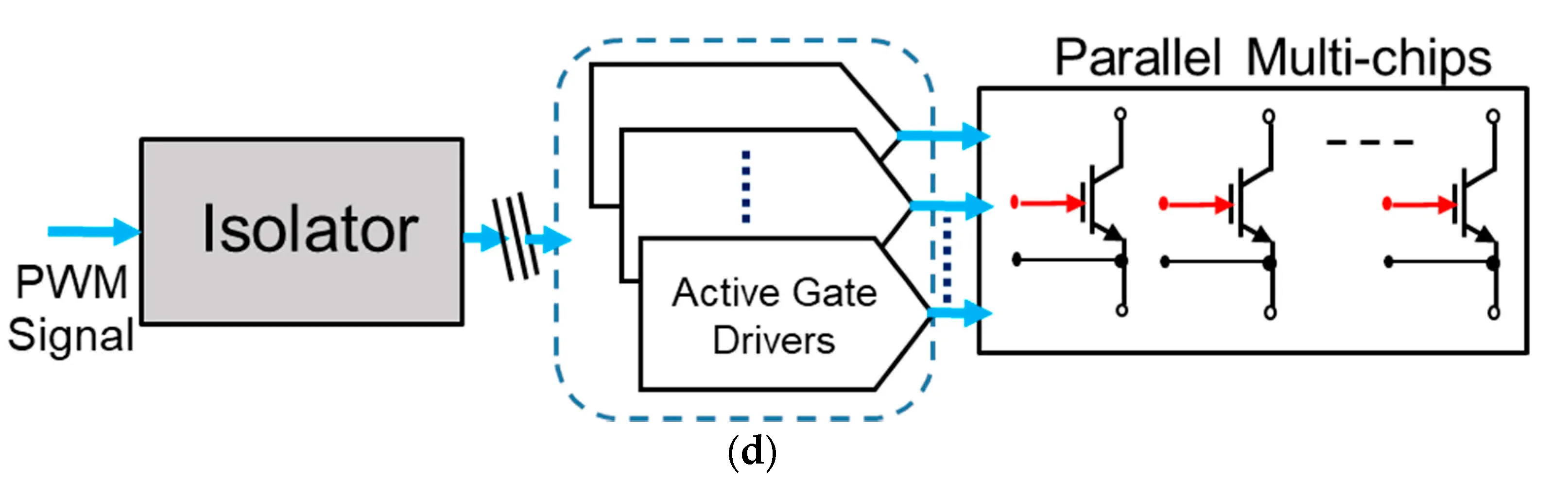
Driver Direct Paralleling (One-to-One with Copper Bus)
In this configuration, each IGBT has an independent driver and the modules are connected by copper busbars. This approach lies between hard paralleling and bridge-arm paralleling.
Characteristics
- Each IGBT has an independent driver.
- The IGBT connections approach hard parallel; the AC outputs of the bridge arms are directly connected by copper busbars.
- Emitter circulating currents may still exist, but there is no coupling between different gate loops; switching behavior of each IGBT is relatively independent.
- Lower requirement for tight matching of individual IGBTs.
- Reduced requirement for symmetry of DC bus stray inductance.
- Very high requirement for synchronization of the VGE signals.
- Very high requirement for consistency of the VGE driver supply voltages.
Advantages
- Bridge-arm operation is effectively independent; gate loops do not couple to each other. Even if emitter circulating currents exist, they do not significantly contaminate the VGE waveform with disturbances from other drivers.
- AC-side stray inductances (Ls1, Ls2) are acceptable and can be beneficial: a moderate amount of stray inductance (on the order of hundreds of nH) will attenuate or block high-frequency current coupling between bridge arms.
- Minor mismatches in the system (DC bus stray inductance asymmetry, VGEth differences, tdon/tdoff differences) are less likely to cause issues and can often be ignored.
- Overall paralleling design risk is substantially reduced.
Key requirements
- When drivers are directly paralleled and the AC stray inductances are small, tight synchronization is required: the time difference from receiving the PWM command to driver action must be very small, with narrow and stable jitter.
- The supply voltages for the two paralleled drivers must be highly consistent.
Implementation Example: CONCEPT Driver Direct Paralleling
CONCEPT proposed a driver direct paralleling approach. In their SCALE-2 family, when using magnetic isolation, the PWM transmission delay is about 80 ns ± 4 ns, and this precise timing supports driver direct paralleling. The auxiliary chip's voltage regulation helps maintain consistent driver supply voltage. Examples of devices using the direct paralleling approach include the 1SP0635 and 1SP0335 series.
IGBT Current Sharing Test Method
For static current sharing tests, use a flexible current probe to measure the bridge-arm output currents and their RMS values to evaluate consistency between arms. When measuring I1 and I2 with a flexible probe, spikes may appear; these spikes correspond to commutation currents flowing through L1 and L2 and should be mitigated by appropriate layout and stray inductance control.


