ALLPCB


As a hobbyist diving into the world of electronics, understanding PCB diagnostics is a game-changer. Whether you're troubleshooting a DIY project or refining an Arduino setup, knowing how to identify and fix issues on a printed circuit board (PCB) can save you time, money, and frustration. In this comprehensive guide, we'll explore the essentials of DIY PCB diagnostic techniques, component-level diagnostics, the best PCB testing equipment for hobbyists, how to find faulty components, and even how to set up Arduino testing environments. Let’s get started with everything you need to know to master PCB diagnostics.
Why PCB Diagnostics Matter for Hobbyists
PCBs are the backbone of most electronic devices, connecting components like resistors, capacitors, and microcontrollers. When something goes wrong, pinpointing the issue can feel like finding a needle in a haystack. That’s where PCB diagnostics come in. By learning how to test and troubleshoot at a component level, hobbyists can avoid scrapping entire boards and instead repair specific faults. This skill not only saves resources but also deepens your understanding of electronics, making you a better builder and problem-solver.
Getting Started with DIY PCB Diagnostic
DIY PCB diagnostic is all about using accessible tools and methods to identify issues on your board. The process begins with a visual inspection and progresses to more advanced testing. Here’s how you can start troubleshooting your PCBs at home.
Step 1: Visual Inspection
Before grabbing any tools, take a close look at your PCB. Check for obvious signs of damage like burnt components, cracked solder joints, or disconnected traces. A magnifying glass or a smartphone camera with zoom can help spot tiny issues. Look for discoloration, which might indicate overheating (often around 150°C or higher for some components), or loose wires that could disrupt connectivity.
Step 2: Power Check
Ensure the board is receiving the correct voltage. Use a multimeter to measure the input voltage and compare it to the expected value (e.g., 5V for many Arduino-based projects). If the voltage is off by more than 10%, there could be an issue with the power supply or a short circuit on the board.
Step 3: Continuity Testing
Continuity testing helps verify that traces on the PCB are intact. Set your multimeter to continuity mode and touch the probes to two points on a trace. A beep indicates a good connection, while silence suggests a break. This method is crucial for finding open circuits, which can halt signal flow.
Component-Level Diagnostic: Digging Deeper
Once you’ve ruled out obvious issues, it’s time for component-level diagnostic. This involves testing individual parts on the PCB to see if they’re functioning as expected. Here’s how to approach it as a hobbyist.
Testing Resistors
Resistors limit current flow, and a faulty one can throw off an entire circuit. Use a multimeter in resistance mode to measure the resistor’s value. Compare it to the color code or printed value (e.g., a 1kΩ resistor should read close to 1000 ohms). A reading of infinity or zero indicates a failed resistor.
Testing Capacitors
Capacitors store charge, and a bad one can cause power issues. While in-circuit testing is tricky due to interference from other components, you can use a multimeter with capacitance mode if available. Otherwise, desolder the capacitor and test it standalone. Look for readings far outside the labeled value (e.g., a 10μF capacitor reading 1μF or less is likely defective).
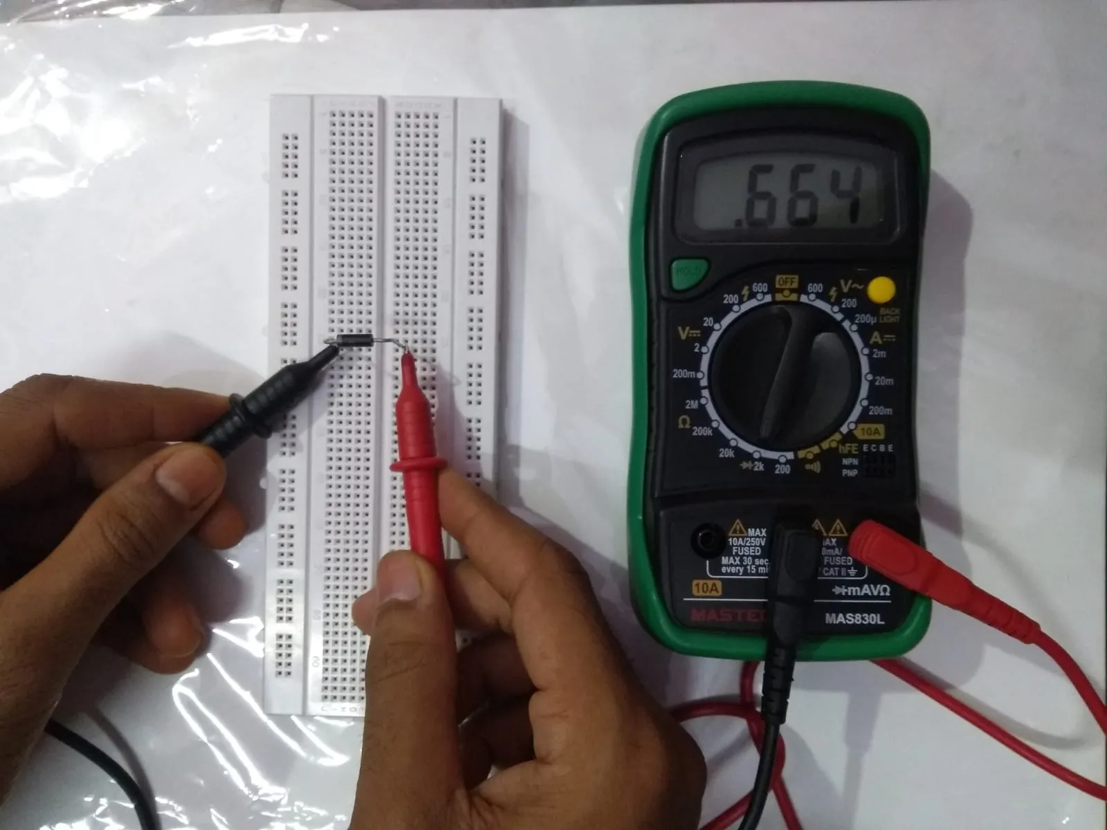
Testing Diodes and Transistors
Diodes should allow current in one direction only. Use the diode mode on your multimeter to test for a voltage drop (typically 0.6V for silicon diodes) in the forward direction and no reading in reverse. For transistors, check each junction (base-emitter, base-collector) using the same diode mode to ensure they behave as expected.
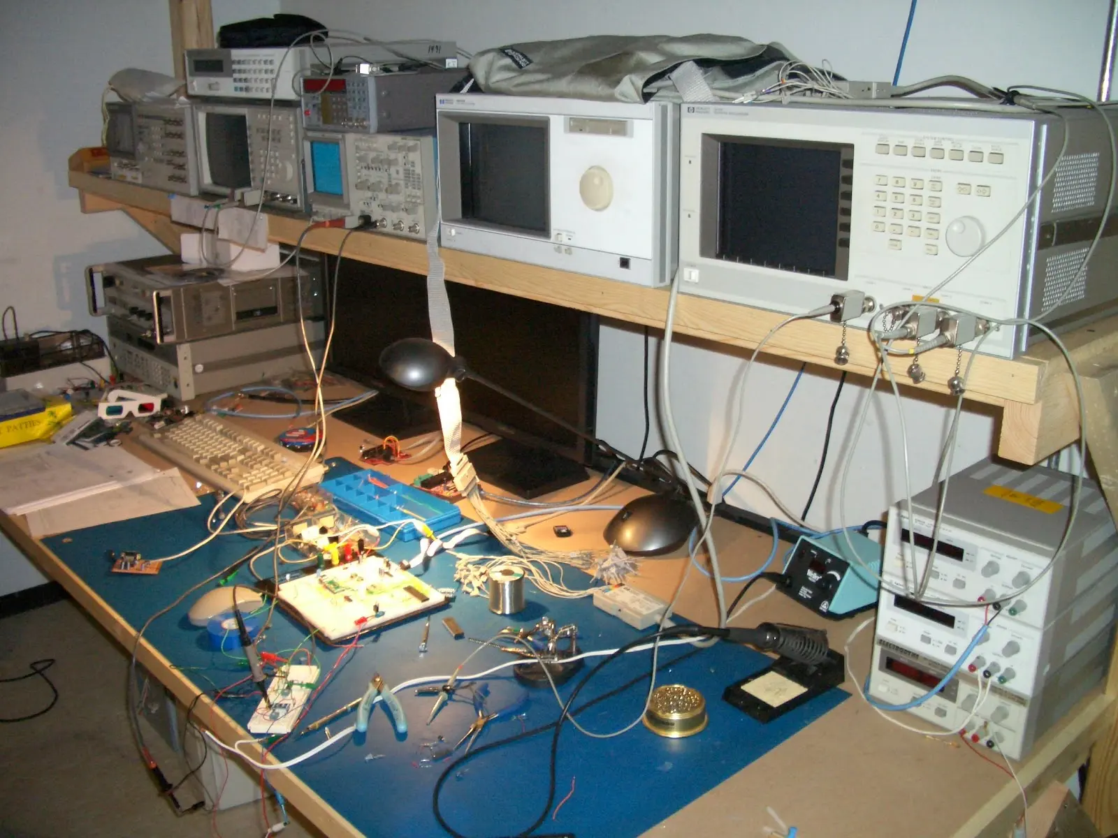
PCB Testing Equipment for Hobbyists
Having the right tools makes PCB diagnostics much easier. Here are some affordable and essential pieces of PCB testing equipment for hobbyists to build their toolkit.
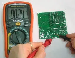
Digital Multimeter (DMM)
A DMM is the most versatile tool for any electronics hobbyist. It can measure voltage, current, resistance, and often capacitance or continuity. Look for one with a range of 0-20V DC and 0-200mA for small projects. Prices start at around $15 for basic models.
Oscilloscope (Optional but Useful)
For more advanced diagnostics, an oscilloscope lets you visualize signals over time. You can spot issues like noise or incorrect waveforms (e.g., a square wave at 1kHz looking distorted). Entry-level USB oscilloscopes are available for under $50 and work well for hobbyist needs.
Component Tester
Devices like transistor testers or multifunction testers can identify and measure components automatically. They’re handy for quickly checking resistors, capacitors, and transistors without manual calculations. Many are priced between $10 and $30 online.
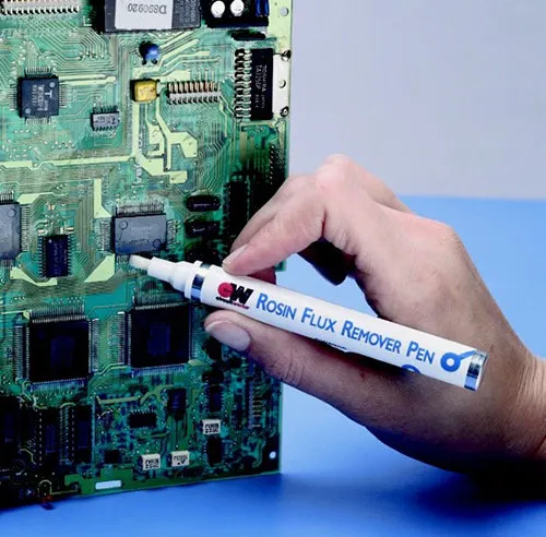
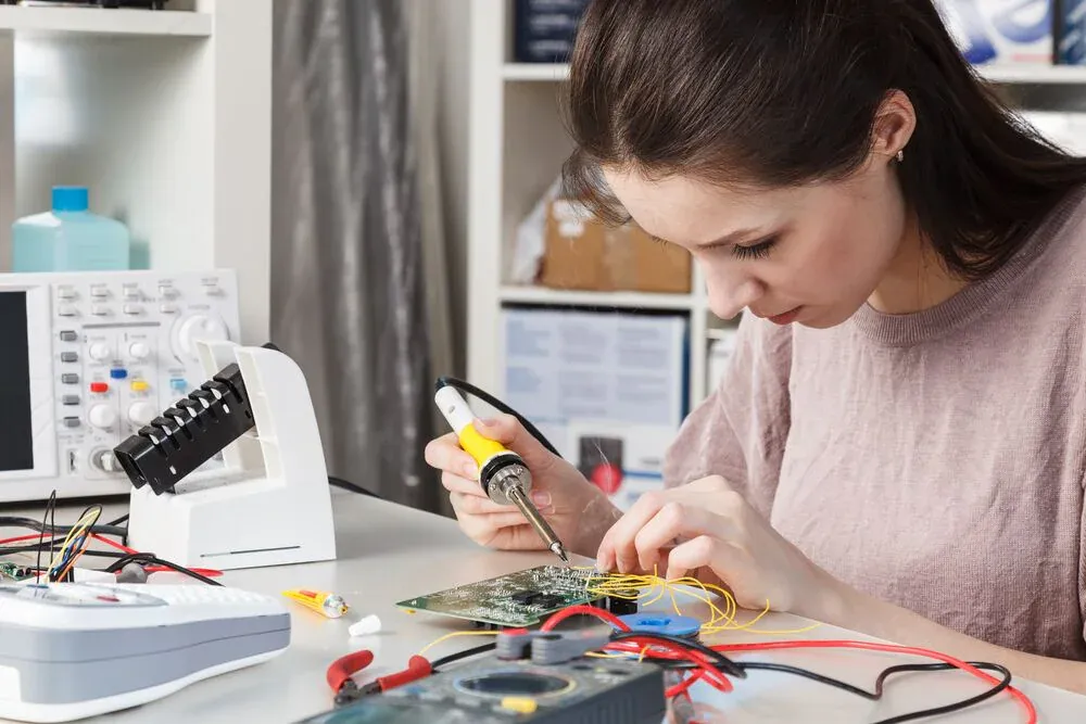
Soldering Tools
A soldering iron (25-40W) and desoldering pump are essential for replacing faulty components. Keep spare solder and flux handy for clean joints. A basic soldering kit can cost as little as $20.
How to Find Faulty Components on a PCB
Finding faulty components is often the hardest part of PCB diagnostics. Here’s a systematic approach to narrow down the problem.
Divide and Conquer
Break the circuit into smaller sections. Test power rails first, then move to individual blocks (e.g., input stage, processing stage). If a section isn’t outputting the expected voltage or signal (like 3.3V dropping to 1V), focus there.
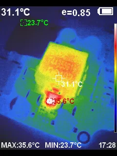
Use a Thermal Camera (If Available)
A thermal camera can reveal hot spots on the board, often indicating a short circuit or overworked component. Components running above 80°C without reason are suspect. Budget thermal camera attachments for smartphones start at around $200, though this is optional.
Signal Tracing
Use a multimeter or oscilloscope to trace signals through the circuit. Start at the input and check each stage. If a signal drops or distorts (e.g., a 5V pulse disappearing), the issue lies before that point. This method is time-consuming but effective for complex boards.
Swap and Test
If you suspect a specific component, replace it with a known good one and test the board. For example, swapping a 10kΩ resistor with a new one might restore functionality, confirming the original was faulty.
Arduino Testing Setup for PCB Diagnostics
Arduino boards are a staple in hobbyist projects, and they can also be powerful tools for PCB diagnostics. Setting up an Arduino testing environment can help you test components and circuits interactively.
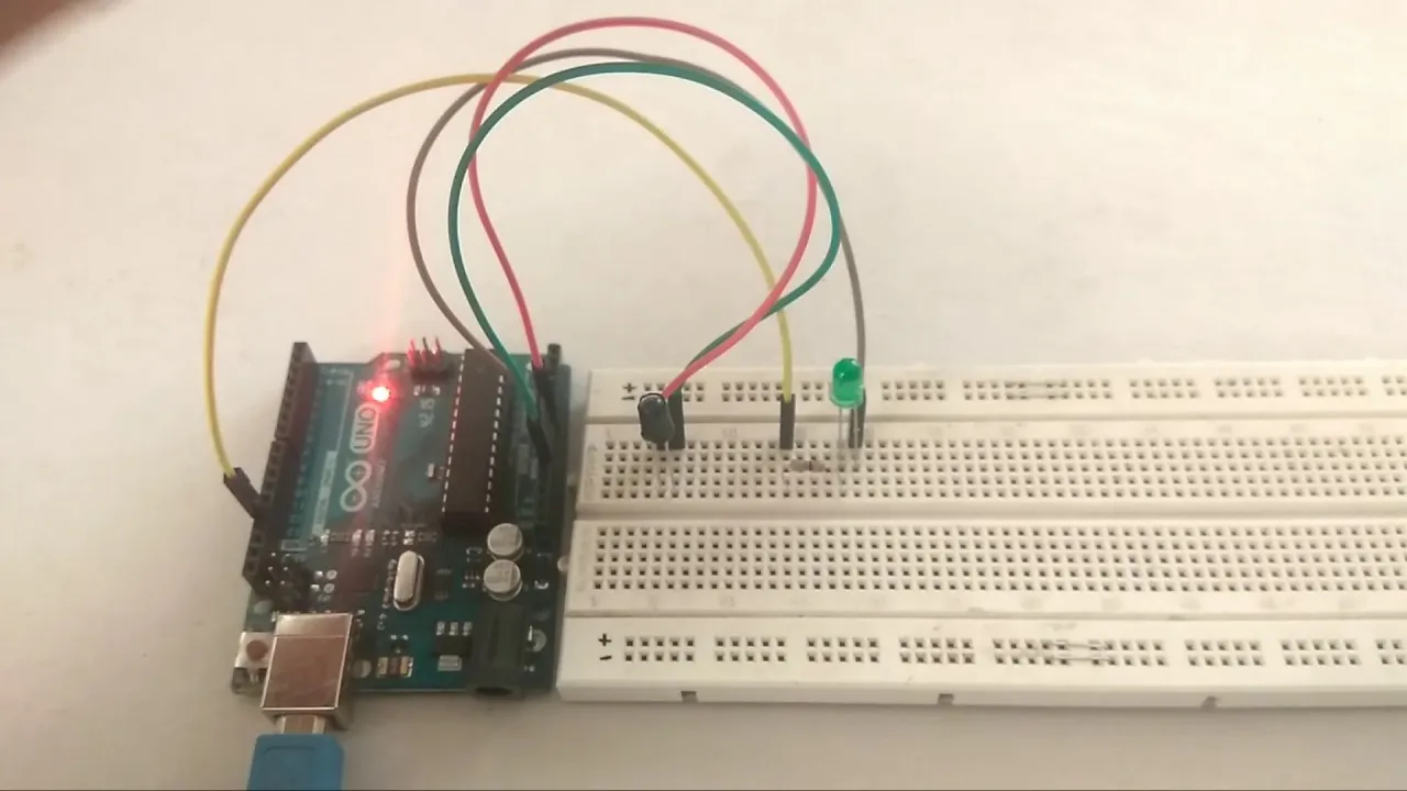
Basic Arduino Setup for Testing
Start with a basic Arduino board (like the Uno, costing around $25) and a breadboard. Connect your PCB or components to the Arduino’s digital or analog pins. Use the Arduino IDE to write simple test scripts, such as reading voltage levels or toggling outputs.
Testing Sensors and Inputs
If your PCB includes sensors, connect their outputs to an Arduino analog pin. Write a sketch to read the value and display it via the Serial Monitor. For example, a photoresistor should output a range of 0-1023; a flat reading of 0 suggests a wiring or component failure.
Simulating Signals
Use the Arduino to generate test signals for your PCB. For instance, program it to output a 1kHz square wave on a digital pin and feed this into your circuit. Use a multimeter or oscilloscope to check if the signal passes through as expected. If it doesn’t, you’ve isolated the problem area.
Power Supply Testing
Arduino boards often have 5V and 3.3V pins. Use these to power small sections of your PCB during testing. Monitor current draw using a multimeter in series; a draw exceeding 100mA on a simple circuit might indicate a short.
Common PCB Diagnostic Challenges and Solutions
Even with the right tools, PCB diagnostics can be tricky. Here are some common hurdles hobbyists face and how to overcome them.
Hidden Shorts
Short circuits between traces or under components are hard to spot. Use a multimeter in continuity mode to test between adjacent traces or pads. If there’s a connection where there shouldn’t be, carefully inspect for solder bridges or damaged insulation.
In-Circuit Testing Limitations
Testing components while soldered to the board can give false readings due to parallel paths. When in doubt, desolder the component and test it separately. This takes time but ensures accuracy.
Complex Circuits
For boards with many components, diagnostics feel overwhelming. Focus on symptoms: if there’s no output, start at the input and work forward. Document each test (e.g., “Pin 3 reads 2.1V, expected 5V”) to avoid confusion.
Tips for Preventing PCB Issues in Future Projects
While diagnostics are crucial, prevention is even better. Here are tips to minimize faults in your future PCB designs and builds.
- Double-Check Schematics: Before ordering or assembling a PCB, verify every connection in your design software. A single wrong trace can cause hours of troubleshooting.
- Use Quality Components: Cheap or salvaged parts are more likely to fail. Invest in reliable components rated for your project’s needs (e.g., capacitors with a 25V rating for a 12V circuit).
- Practice Good Soldering: Avoid cold joints by heating both the pad and component lead before applying solder. A joint should look shiny and concave, not dull or bulbous.
- Test Incrementally: Assemble and test your PCB in stages. Power up after adding a few components to catch issues early.
Conclusion: Mastering PCB Diagnostics as a Hobbyist
PCB diagnostics might seem daunting at first, but with the right approach and tools, any hobbyist can become proficient. From DIY PCB diagnostic basics to component-level testing, using the best PCB testing equipment for hobbyists, finding faulty components, and setting up an Arduino testing environment, this guide covers the essentials to get you started. By practicing these techniques, you’ll not only fix broken boards but also build better projects in the long run. Keep learning, stay patient, and soon you’ll be troubleshooting like a pro.