 ALLPCB


Flex PCBs, or flexible printed circuit boards, are transforming the world of electronics with their unique ability to bend, fold, and adapt to various shapes. If you're curious about Flex PCB shape, flexible circuit board design, dynamic flex PCB applications, bend radius flex PCB, or flex PCB materials, you're in the right place. In this comprehensive guide, we'll dive deep into how these innovative boards work, why their design matters, and where they shine in real-world applications. Whether you're an engineer, designer, or tech enthusiast, this blog will provide actionable insights to help you understand and leverage flex PCBs in your projects.
What Are Flex PCBs and Why Do They Matter?
Flex PCBs are thin, lightweight circuit boards made from flexible materials that allow them to bend and conform to different shapes without breaking. Unlike traditional rigid PCBs, which are stiff and fixed, flex PCBs offer a solution for compact, dynamic, and space-constrained designs. Their importance lies in their ability to fit into tight spaces, reduce weight, and improve reliability in applications where movement or vibration is a factor.
In industries like wearables, medical devices, and aerospace, flex PCBs are game-changers. They enable smaller, more efficient designs while maintaining high performance. As we explore flexible circuit board design and other key aspects, you'll see how these boards are shaping the future of electronics.

Understanding Flex PCB Shape and Its Impact on Design
The Flex PCB shape is a critical factor in how these boards function and fit into a product. Unlike rigid boards, flex PCBs can be designed in almost any shape to match the contours of a device. This adaptability allows engineers to create electronics that are not only functional but also aesthetically integrated into the product's design.
For instance, in a smartwatch, the flex PCB might be shaped to wrap around the curved interior of the device, saving space and ensuring a snug fit. The shape also affects how the board handles stress during bending or flexing. A poorly designed shape could lead to cracks or failures in the copper traces. To avoid this, designers must consider the board's final form during the planning phase, ensuring that the shape aligns with the product's mechanical requirements.
When designing the shape, it's also vital to account for the placement of components. Heavy or rigid components should be placed in areas with minimal bending to prevent damage. By optimizing the Flex PCB shape, designers can enhance both functionality and durability.
Key Principles of Flexible Circuit Board Design
Designing a flex PCB is different from working with rigid boards due to the unique challenges of flexibility and movement. Here are some essential principles for flexible circuit board design that every engineer should know:
- Trace Layout: Copper traces on a flex PCB must be routed to avoid stress points. Curved traces are often better than sharp angles, as they distribute stress more evenly during bending. A common guideline is to keep trace widths at least 0.006 inches (0.15 mm) for better reliability.
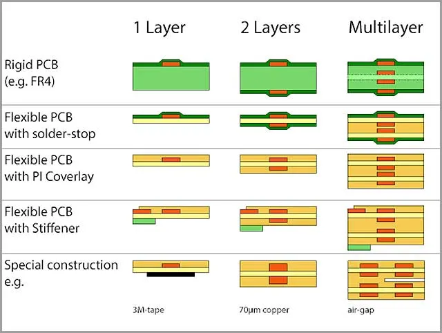
- Layer Stacking: Flex PCBs often have multiple layers, but fewer layers are preferred for flexibility. A typical stack-up might include a polyimide base layer, copper traces, and a coverlay for protection. Balancing the number of layers with flexibility needs is key.
- Component Placement: Place components in areas that experience the least bending. For dynamic flex designs, where the board bends repeatedly, components should be secured with additional adhesives or supports.
- Stiffeners: In some designs, stiffeners (rigid materials) are added to specific areas of the flex PCB to support components or connectors. These must be carefully integrated to avoid hindering flexibility where it's needed.
By following these principles, designers can create flex PCBs that are both reliable and efficient. Software tools for PCB layout can simulate bending and stress, helping to refine the design before manufacturing.
Bend Radius in Flex PCBs: Why It Matters
The bend radius flex PCB refers to the minimum radius a flex PCB can be bent without damaging the board or its traces. This is a crucial parameter in design because bending too tightly can cause cracks in the copper or delamination of the layers.
A general rule of thumb is that the bend radius should be at least 10 times the thickness of the flex PCB for static applications (where the board is bent once and stays in place). For dynamic applications (where the board bends repeatedly), the bend radius should be even larger—often 20 times the thickness or more. For example, a 0.1 mm thick flex PCB should have a minimum bend radius of 1 mm for static use and 2 mm for dynamic use.
Material choice also affects the bend radius. Thinner materials like polyimide can handle tighter bends, while thicker or less flexible materials may require a larger radius. Designers must test prototypes under real-world conditions to ensure the bend radius is appropriate for the application.
Exploring Dynamic Flex PCB Applications
Flex PCBs truly shine in dynamic flex PCB applications, where the board must bend or flex repeatedly during use. These applications highlight the unique advantages of flex PCBs over rigid alternatives. Here are some key areas where dynamic flex PCBs are making an impact:
- Wearable Technology: Devices like fitness trackers and smartwatches rely on flex PCBs to fit into curved, compact designs. The boards must withstand constant movement as the wearer moves their wrist.
- Medical Devices: In applications like hearing aids or implantable devices, flex PCBs conform to the shape of the human body while enduring slight movements over time.
- Automotive Systems: Flex PCBs are used in dashboards and sensors, where they must handle vibrations and temperature changes without failing.
- Foldable Electronics: Modern foldable smartphones and tablets use flex PCBs in their hinge areas, allowing the device to open and close thousands of times without damage. Some designs are tested for up to 200,000 folds, showcasing the durability of well-designed flex circuits.
In dynamic applications, the design must prioritize fatigue resistance. This means using materials and layouts that can handle repeated stress without cracking or losing conductivity. Testing for dynamic flexing often involves bending the PCB thousands of times under controlled conditions to simulate real-world use.
Flex PCB Materials: The Foundation of Flexibility
The choice of flex PCB materials plays a huge role in the board's performance, flexibility, and durability. Let's break down the most common materials used in flex PCB manufacturing:
- Polyimide (PI): This is the most widely used base material for flex PCBs due to its excellent flexibility, thermal stability, and chemical resistance. Polyimide can withstand temperatures up to 260°C, making it ideal for high-heat applications.
- Copper Foil: Copper is used for the conductive traces. Rolled annealed (RA) copper is preferred over electrodeposited (ED) copper because it is more flexible and less prone to cracking during bending.
- Coverlay: A protective layer, often made of polyimide or liquid photoimageable (LPI) materials, is applied over the copper traces to insulate and protect them from environmental factors.
- Adhesives: In some designs, adhesives bond the layers together. However, adhesiveless constructions are becoming more common for better flexibility and thermal performance.
The thickness of these materials also matters. A typical polyimide base layer might be 0.025 mm to 0.125 mm thick, depending on the flexibility required. Thinner materials allow for tighter bends but may be less durable, so there's always a trade-off to consider.
Recent advancements in materials have led to the development of ultra-thin polyimide films and high-performance copper foils that improve both flexibility and signal integrity. Staying updated on material innovations can give designers an edge in creating cutting-edge flex PCBs.
Challenges in Flex PCB Design and How to Overcome Them
While flex PCBs offer incredible benefits, they come with unique challenges. Addressing these early in the design process can save time and cost during manufacturing. Here are some common issues and solutions:
- Mechanical Stress: Repeated bending can cause fatigue in copper traces. Solution: Use wider traces and avoid sharp bends in dynamic areas.
- Signal Integrity: Flex PCBs can suffer from signal loss or interference, especially at high frequencies. Solution: Keep trace lengths short and use proper grounding techniques. For high-speed signals, impedance control is critical—targeting values like 50 ohms for single-ended traces or 100 ohms for differential pairs.
- Manufacturing Complexity: Flex PCBs are more complex to produce than rigid boards, leading to higher costs. Solution: Simplify the design where possible, such as reducing the number of layers or minimizing tight bend areas.
Collaboration between designers and manufacturers is essential to tackle these challenges. Early feedback on design files can help identify potential issues before production begins.
Tips for Optimizing Flex PCB Performance
To get the most out of your flex PCB, consider these practical tips:
- Test Prototypes: Always create and test prototypes under real-world conditions to validate the design, especially for dynamic applications.
- Balance Cost and Performance: While high-end materials improve performance, they also increase costs. Choose materials that meet your needs without over-engineering.
- Work with Experts: Partner with experienced manufacturers who can provide guidance on design rules, material selection, and testing.
By focusing on these strategies, you can ensure your flex PCB performs reliably while staying within budget.
Conclusion: The Future of Flex PCBs
Flex PCBs are revolutionizing electronics with their ability to adapt to unique shapes, withstand dynamic movement, and fit into compact spaces. From understanding Flex PCB shape and bend radius flex PCB to exploring dynamic flex PCB applications and flex PCB materials, we've covered the essentials of flexible circuit board design. As technology advances, flex PCBs will continue to play a vital role in wearables, medical devices, automotive systems, and beyond.
Whether you're designing a new product or looking to improve an existing one, flex PCBs offer endless possibilities. With careful planning, the right materials, and a focus on performance, you can harness the full potential of these innovative circuits in your next project.


