In-flight entertainment (IFE) systems are a vital part of modern air travel, keeping passengers engaged with movies, music, and connectivity during long flights. But behind these systems are printed circuit boards (PCBs) that must withstand the harsh conditions of aerospace environments while meeting strict industry standards. So, how do you design robust PCBs for in-flight entertainment that comply with aerospace rules? This blog dives deep into the essentials of aerospace PCB design rules, in-flight entertainment PCB certification, AS9100 PCB requirements, and the role of IPC 6012ES in aerospace applications. Whether you're an engineer or a project manager, you'll find actionable insights to ensure your IFE PCBs are reliable and compliant.
Why Aerospace Standards Matter for In-Flight Entertainment PCBs
Aerospace environments are unlike any other. PCBs in IFE systems face extreme temperatures, vibrations, and pressure changes, all while needing to deliver flawless performance. A single failure can disrupt passenger experience or, worse, compromise safety systems tied to the aircraft's electronics. This is why adhering to aerospace PCB design rules and certifications is non-negotiable. Standards like AS9100 and IPC 6012ES provide a framework to ensure quality, reliability, and safety, helping manufacturers build trust and meet regulatory demands.
In this post, we'll break down the specific requirements and best practices for designing IFE PCBs that stand up to these challenges. From material selection to testing protocols, you'll get a clear roadmap for success.
Understanding Aerospace PCB Design Rules for IFE Systems
Designing PCBs for aerospace applications, especially in-flight entertainment, requires a deep understanding of unique constraints. These systems must be lightweight, compact, and energy-efficient while enduring the rigors of flight. Here are the key aerospace PCB design rules to follow:
1. Material Selection for Harsh Environments
The materials used in IFE PCBs must handle temperature swings from -55°C to 85°C, as well as high humidity and potential corrosion. High-performance laminates like polyimide or FR-4 with enhanced thermal properties are often chosen for their durability. Copper thickness also plays a role, with a minimum of 1 oz per square foot recommended to ensure conductivity under stress.
2. Minimizing Electromagnetic Interference (EMI)
IFE systems operate near sensitive avionics equipment, so EMI control is critical. Use ground planes and shielding techniques to reduce noise. Keep signal traces short and avoid high-speed signals running parallel to power lines. Aim for impedance values around 50 ohms for high-frequency signals to maintain integrity.
3. Mechanical Strength and Vibration Resistance
Aircraft experience constant vibration during flight, which can crack solder joints or dislodge components. Design PCBs with a minimum dielectric thickness of 3.5 mil to provide mechanical strength. Additionally, secure components with conformal coatings or underfill to prevent movement.
4. Compact and Lightweight Design
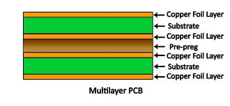
Space and weight are at a premium in aerospace. Use multilayer PCBs to reduce footprint while maintaining functionality. Optimize trace widths (typically 6-8 mil for standard signals) to save space without sacrificing performance.
By following these aerospace PCB design rules, you ensure that IFE systems remain operational under the toughest conditions, providing passengers with uninterrupted service.
In-Flight Entertainment PCB Certification: What You Need to Know
Certification is a cornerstone of aerospace electronics. In-flight entertainment PCB certification ensures that every board meets safety, reliability, and performance benchmarks before it’s installed in an aircraft. Let’s explore the key certifications and processes involved.
Compliance with Regulatory Bodies
IFE PCBs must comply with standards set by organizations like the Federal Aviation Administration (FAA) and the European Union Aviation Safety Agency (EASA). These bodies mandate rigorous testing for environmental resilience, fire resistance, and electrical safety. Certification often involves submitting detailed documentation of design, materials, and test results for approval.
Environmental and Durability Testing
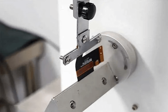
Before certification, PCBs undergo tests like thermal cycling (exposing boards to temperature extremes), vibration testing (simulating takeoff and landing stresses), and humidity exposure (up to 95% relative humidity). Passing these tests proves the board can operate reliably at 30,000 feet.
Traceability and Documentation
Every component and process in IFE PCB production must be traceable. This means maintaining records of raw materials, manufacturing steps, and test outcomes. Certification bodies often audit these records to verify compliance with industry standards.
Securing in-flight entertainment PCB certification isn’t just about meeting requirements—it’s about building confidence in your product’s reliability for airlines and passengers alike.
AS9100 PCB Requirements: Ensuring Quality in Aerospace
AS9100 is the gold standard for quality management in the aerospace industry. This certification, based on ISO 9001 but tailored for aerospace, outlines strict AS9100 PCB requirements that manufacturers must follow. Here’s how it applies to IFE PCBs:
1. Risk Management
AS9100 emphasizes identifying and mitigating risks at every stage of PCB production. For IFE systems, this could mean assessing the risk of signal failure in critical display units or power loss in audio systems. Manufacturers must develop contingency plans and test them regularly.
2. Supplier and Process Control
Every supplier providing materials or services for IFE PCBs must meet AS9100 standards. This includes vetting laminate providers for consistent quality and ensuring assembly processes adhere to tight tolerances (e.g., ±0.1 mm for component placement).
3. Continuous Improvement
AS9100 requires ongoing evaluation and improvement of processes. For example, if a batch of IFE PCBs shows a higher-than-average failure rate during testing, the root cause must be analyzed, and corrective actions implemented to prevent recurrence.
4. Customer Focus
Meeting airline expectations is a core part of AS9100. This means designing IFE PCBs that not only comply with technical standards but also align with customer needs for cost, delivery timelines, and performance.
Adhering to AS9100 PCB requirements ensures that your IFE systems are built with the highest quality, reducing the likelihood of in-flight failures and costly recalls.
IPC 6012ES in Aerospace: The Benchmark for PCB Performance
IPC 6012ES is a specific standard for space and military avionics PCBs, often applied to aerospace applications like IFE systems. It builds on the broader IPC 6012 standard by adding stringent requirements for high-reliability environments. Here’s how IPC 6012ES in aerospace impacts IFE PCB design and manufacturing:
1. Enhanced Material and Construction Standards
IPC 6012ES mandates the use of high-reliability materials that resist thermal and mechanical stress. For instance, it specifies minimum copper plating thickness in vias (typically 1 mil or 25 microns) to prevent cracking under vibration.
2. Tight Tolerances for Fabrication
The standard sets precise limits for fabrication defects. For example, it allows no more than 0.5% voiding in solder joints and requires perfect registration between layers (within ±2 mil). These tolerances ensure IFE PCBs perform consistently during long flights.
3. Rigorous Inspection and Testing
IPC 6012ES requires microsection analysis to check internal structures of the PCB, as well as electrical testing to verify signal integrity at speeds up to 10 Gbps for modern IFE systems. Any deviation from the standard can lead to rejection of the entire batch.
4. Focus on Reliability for Critical Applications
In aerospace, there’s no room for error. IPC 6012ES ensures that IFE PCBs can operate without failure for thousands of hours, even in extreme conditions like rapid depressurization or lightning strikes.
By aligning with IPC 6012ES in aerospace, manufacturers can guarantee that their IFE PCBs meet the highest performance and reliability benchmarks, ensuring passenger satisfaction and safety.
Best Practices for Designing Robust IFE PCBs
Beyond meeting standards, there are practical steps you can take to enhance the robustness of in-flight entertainment PCBs. These best practices bridge the gap between compliance and real-world performance.
1. Use Simulation Tools Early
Before fabrication, use simulation software to test your PCB design for thermal hotspots, signal delays, and EMI issues. For instance, simulate high-speed video signals at 4K resolution to ensure they maintain clarity across the IFE system.
2. Prioritize Redundancy
Build redundancy into critical circuits, such as power supplies for seat-back screens. If one pathway fails, a backup can take over, preventing system-wide outages.
3. Opt for Robust Connectors
Connectors in IFE PCBs must withstand frequent plugging and unplugging by maintenance crews. Choose connectors rated for at least 500 mating cycles and resistant to corrosion.
4. Plan for Easy Maintenance
Design PCBs with accessible test points and modular components. This allows airline technicians to quickly diagnose and replace faulty parts without grounding the aircraft for extended periods.
These practices, combined with adherence to aerospace standards, create IFE PCBs that are not only compliant but also exceptionally reliable.
Challenges in Designing IFE PCBs and How to Overcome Them
Designing PCBs for in-flight entertainment isn’t without hurdles. Here are common challenges and solutions to keep your project on track:
Balancing Cost and Quality
High-reliability materials and certifications drive up costs. To manage expenses, focus on optimizing designs early to reduce material waste and streamline manufacturing steps without compromising on standards.
Meeting Tight Deadlines
Aerospace projects often have aggressive timelines. Partner with experienced manufacturers who can provide rapid prototyping and testing to speed up certification without cutting corners.
Navigating Complex Standards
Standards like AS9100 and IPC 6012ES can be overwhelming. Invest in training for your team or consult with experts familiar with aerospace PCB design rules to ensure compliance from the start.
By anticipating these challenges and planning accordingly, you can deliver IFE PCBs that meet both technical and business goals.
Conclusion: Building the Future of In-Flight Entertainment
Designing robust in-flight entertainment PCBs is a complex but rewarding task. By following aerospace PCB design rules, securing in-flight entertainment PCB certification, meeting AS9100 PCB requirements, and adhering to IPC 6012ES in aerospace standards, you can create systems that enhance passenger experience while ensuring safety and reliability. Every step—from material selection to testing—plays a crucial role in building trust with airlines and regulatory bodies.
At ALLPCB, we’re committed to supporting engineers and manufacturers in navigating these challenges. With a focus on quality and precision, we provide the tools and expertise needed to bring your IFE PCB designs to life. Let’s work together to elevate the standard of aerospace electronics and keep passengers connected, entertained, and safe in the skies.
 ALLPCB


