Creating a battery charger PCB that ensures optimal performance and reliability requires careful attention to layout techniques, especially for maintaining signal integrity. Whether you're an electronics engineer or a hobbyist, understanding how to design a PCB for a battery charger can prevent issues like noise interference and power instability. In this comprehensive guide, we’ll explore the key aspects of battery charger PCB layout, focusing on signal integrity PCB design, noise reduction PCB strategies, effective ground plane design, and the role of decoupling capacitors PCB placement. Let’s dive into the essential techniques to help you build a high-performing battery charger PCB.
Why Signal Integrity Matters in Battery Charger PCB Design
Signal integrity is the foundation of any reliable electronic design, especially in a battery charger PCB where power delivery and control signals must coexist without interference. Poor signal integrity can lead to erratic charging behavior, reduced efficiency, or even damage to the battery or connected devices. For instance, high-frequency switching in chargers can generate noise that disrupts sensitive control signals if not managed properly.
In a typical battery charger circuit, you’re dealing with currents ranging from a few hundred milliamps to several amps, and switching frequencies often exceed 100 kHz. Without a well-thought-out battery charger PCB layout, electromagnetic interference (EMI) can degrade performance. This is why mastering signal integrity PCB design is critical. Let’s break down the core techniques to achieve this.
Key Principles of Battery Charger PCB Layout
The layout of a battery charger PCB directly impacts its efficiency and reliability. A poorly designed layout can introduce parasitic inductance and capacitance, leading to voltage spikes or signal delays. Here are the essential principles to follow for an effective battery charger PCB layout.
1. Component Placement for Optimal Flow
Start by placing critical components such as the power MOSFETs, inductors, and input/output capacitors as close as possible to each other. This minimizes the loop area for high-current paths, reducing parasitic inductance. For example, in a buck converter-based charger design, the input capacitor should be within 1-2 mm of the switching regulator’s input pin to stabilize the voltage during switching events.
Keep sensitive components, like feedback resistors or control ICs, away from high-current or noisy areas. Place them near the ground plane to shield them from interference. A logical flow of power from input to output also helps maintain signal integrity PCB design by avoiding unnecessary crossovers of power and signal traces.
2. Short and Direct Power Traces
Power traces carry significant current, so they must be short, wide, and direct. For a charger handling 2A of current, a trace width of at least 40 mils (1 mm) with a copper thickness of 1 oz/ft2 is recommended to minimize resistance and heat buildup. Use vias sparingly in power paths, as they add inductance—aim for no more than 2-3 vias per path if unavoidable.
Ground Plane Design: The Backbone of Noise Reduction
A solid ground plane design is one of the most effective ways to achieve noise reduction PCB performance in a battery charger. The ground plane acts as a low-impedance return path for currents and helps shield sensitive signals from interference.
1. Use a Continuous Ground Plane
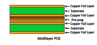
Avoid splitting the ground plane unless absolutely necessary for isolating analog and digital sections. A continuous ground plane under the entire circuit reduces loop inductance and provides a stable reference for all signals. For a two-layer PCB, dedicate one layer primarily to ground, connecting it with multiple vias to the top layer’s ground points.
For a four-layer board, assign an inner layer as a dedicated ground plane. This setup can reduce EMI by up to 20 dB compared to a split or poorly connected ground, ensuring better signal integrity PCB design.
2. Strategic Ground Connections
Connect all ground pins of components directly to the ground plane using short traces or vias. For high-current components like power MOSFETs, use multiple vias to the ground plane to handle the current density. This approach minimizes voltage drops and ground bounce, which are common sources of noise in battery chargers.
Noise Reduction Techniques for Battery Charger PCBs
Noise is a major challenge in battery charger designs due to the high-frequency switching and rapid current changes. Implementing noise reduction PCB strategies can significantly improve performance and prevent issues like erratic charging or EMI compliance failures.
1. Minimize Switching Noise
Switching regulators in battery chargers often operate at frequencies between 100 kHz and 2 MHz, generating noise that can couple into nearby traces. To reduce this, keep the switching node (the connection between the MOSFET and inductor) as small as possible—ideally under 5 mm in length. Use a snubber circuit (a small resistor and capacitor in parallel) across the switching node if voltage spikes exceed 10% of the input voltage.
2. Shield Sensitive Traces
Route sensitive signal traces, such as those carrying feedback or control signals, away from high-current or switching areas. If they must cross noisy areas, route them on a different layer with a ground plane in between to act as a shield. This practice is vital for maintaining signal integrity PCB design in high-noise environments.
The Role of Decoupling Capacitors in PCB Design
Decoupling capacitors PCB placement is a critical factor in stabilizing power delivery and reducing noise. These capacitors act as local energy reservoirs, supplying instantaneous current to components during switching events and filtering out high-frequency noise.
1. Placement and Sizing of Decoupling Capacitors
Place decoupling capacitors as close as possible to the power pins of ICs and switching regulators—ideally within 1 mm. For a typical control IC in a battery charger, a 0.1 μF ceramic capacitor is often sufficient to handle high-frequency noise, while a 10 μF capacitor near the input can manage bulk energy needs. Use low-ESR (equivalent series resistance) capacitors to minimize impedance at high frequencies, targeting an ESR below 0.1 ohms.
2. Multiple Capacitors for Broad Frequency Coverage
Since different capacitors are effective at different frequency ranges, combine values like 0.01 μF, 0.1 μF, and 1 μF near critical components. This ensures noise suppression across a wide spectrum, from 100 kHz to 100 MHz, enhancing noise reduction PCB performance.
Thermal Management in Battery Charger PCB Layout
Battery chargers often handle significant power, leading to heat generation that can affect both performance and component lifespan. A good battery charger PCB layout must address thermal issues to maintain reliability.
1. Use Thermal Vias and Copper Pours
For components like power MOSFETs or regulators that dissipate heat, place thermal vias under their pads to connect to a large copper area or ground plane on the opposite layer. A grid of 4-6 vias with a diameter of 0.3 mm can effectively transfer heat away from the component. Ensure the copper pour is at least 500 mm2 to act as a heat sink.
2. Adequate Spacing for Airflow
Space out heat-generating components to prevent localized hot spots. If using an enclosure, consider adding ventilation or a small heat sink for high-power designs delivering over 10W. Proper thermal management ties directly into maintaining signal integrity PCB design by preventing thermal noise from affecting sensitive circuits.
Testing and Validation for Signal Integrity
Once your PCB layout is complete, testing is crucial to verify signal integrity PCB design and overall performance. Use an oscilloscope to measure voltage ripple on the output; aim for less than 1% of the nominal voltage (e.g., under 50 mV for a 5V output). Check for EMI using a spectrum analyzer to ensure compliance with standards like FCC Part 15 or CISPR 22, targeting emissions below -40 dBm at critical frequencies.
Simulate high-load conditions (e.g., charging at maximum current) to observe any ground bounce or crosstalk. If issues arise, revisit your ground plane design or adjust the placement of decoupling capacitors PCB to mitigate them.
Common Mistakes to Avoid in Battery Charger PCB Design
Even with the best intentions, certain pitfalls can compromise a battery charger PCB. Avoid these common errors:
- Neglecting Ground Plane Integrity: Splitting the ground plane without a clear reason can disrupt return paths, increasing noise.
- Improper Decoupling Capacitor Placement: Placing capacitors too far from power pins can render them ineffective, leading to voltage fluctuations.
- Overloading Traces: Underestimating current requirements can cause traces to overheat, risking failure. Use trace width calculators to ensure safety.
- Ignoring Thermal Design: Failing to account for heat dissipation can degrade components over time, affecting signal integrity PCB design.
Conclusion: Building a Reliable Battery Charger PCB
Designing a battery charger PCB that excels in performance and reliability is all about mastering the layout for signal integrity PCB design. By focusing on a strategic battery charger PCB layout, implementing robust ground plane design, prioritizing noise reduction PCB techniques, and optimizing decoupling capacitors PCB placement, you can create a charger that operates efficiently and withstands real-world challenges.
Every detail, from component placement to thermal management, plays a role in ensuring your design meets both functional and regulatory requirements. With the actionable tips and techniques shared in this guide, you’re well-equipped to tackle your next battery charger project with confidence. Start applying these principles today to elevate your PCB designs to the next level.
 ALLPCB


