 ALLPCB


Designing a reliable Engine Control Unit (ECU) PCB requires careful selection of components to ensure durability, performance, and safety in the demanding automotive environment. If you're searching for guidance on automotive grade components for ECU PCB, high reliability components for engine control, or specific tips on ECU PCB capacitor selection, ECU PCB resistor selection, and ECU PCB diode selection, you're in the right place. This guide provides a detailed roadmap to choosing the best components for your ECU PCB, ensuring robust performance under harsh conditions like extreme temperatures, vibrations, and electrical noise.
In the following sections, we'll dive deep into the key considerations for component selection, explore specific component types, and offer practical tips to help you build high-performing ECU PCBs for automotive applications. Whether you're an engineer or a designer, this comprehensive resource will equip you with the knowledge to make informed decisions.
Why Component Selection Matters for ECU PCBs
The Engine Control Unit is the brain of a vehicle's engine system, managing critical functions like fuel injection, ignition timing, and emission control. Given its role, the ECU PCB must withstand harsh conditions, including temperature swings from -40°C to 125°C, constant vibrations, and exposure to moisture or contaminants. Choosing automotive grade components for ECU PCB is not just a preference—it's a necessity to ensure reliability and prevent failures that could lead to costly repairs or safety hazards.
Using high reliability components for engine control also helps meet stringent industry standards like AEC-Q100 and AEC-Q200, which define the quality and durability requirements for automotive electronics. Poor component choices can result in issues like signal interference, thermal breakdown, or premature wear, all of which compromise the ECU's performance. Let’s explore how to select the right components to avoid these pitfalls.
Key Factors in Selecting Automotive Grade Components for ECU PCB
Before diving into specific component types, it's important to understand the overarching factors that guide component selection for ECU PCBs. These considerations ensure that every part you choose contributes to the overall reliability and efficiency of the system.
1. Compliance with Automotive Standards
Always prioritize components that meet automotive-specific qualifications, such as the AEC-Q series standards. These standards test components for temperature extremes, thermal cycling, humidity resistance, and mechanical stress. For instance, AEC-Q100 focuses on integrated circuits, while AEC-Q200 covers passive components like resistors and capacitors. Using certified automotive grade components for ECU PCB ensures they can handle the unique challenges of vehicle environments.
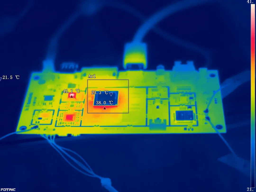
2. Temperature and Environmental Durability
ECU PCBs often operate near the engine, where temperatures can exceed 100°C. Components must have a wide operating temperature range, typically from -40°C to 125°C or higher. Additionally, they should resist corrosion and humidity, as exposure to moisture or chemicals is common in automotive settings.
3. Vibration and Mechanical Stress Resistance
Vehicles are constantly in motion, subjecting ECUs to vibrations and shocks. Components with robust packaging and secure mounting options, such as surface-mount devices (SMDs) with reinforced leads, are ideal for maintaining stability under mechanical stress.
4. Electrical Performance and Noise Immunity
ECUs manage complex signals with strict timing requirements. Components must minimize electrical noise and electromagnetic interference (EMI). For example, capacitors and resistors with low equivalent series resistance (ESR) and tight tolerance values help maintain signal integrity, which is critical for engine control functions.
ECU PCB Capacitor Selection: Ensuring Stability and Noise Reduction
Capacitors play a vital role in ECU PCBs by filtering noise, stabilizing voltage, and storing energy for quick discharge. However, not all capacitors are suitable for automotive applications. Here's how to approach ECU PCB capacitor selection for optimal performance.
Types of Capacitors for ECU PCBs
There are several types of capacitors to consider, each with unique properties:
- Ceramic Capacitors: These are widely used due to their high stability and low ESR. Multilayer ceramic capacitors (MLCCs) with X7R or X8R dielectrics are preferred for automotive ECUs as they maintain capacitance across a wide temperature range (-55°C to 150°C).
- Tantalum Capacitors: Known for high capacitance in a small footprint, tantalum capacitors are useful for decoupling applications. However, ensure they are rated for automotive use, as standard versions may fail under thermal stress.
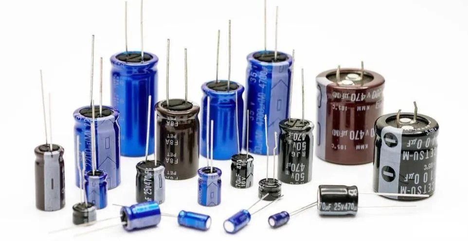
- Aluminum Electrolytic Capacitors: These are suitable for bulk capacitance needs, such as power supply smoothing. Choose versions with extended temperature ratings (up to 125°C) and long lifespan (over 5000 hours at rated temperature).
Key Specifications to Consider
When selecting capacitors, pay attention to:
- Voltage Rating: Choose a capacitor with a voltage rating at least 50% higher than the maximum operating voltage to account for surges. For a 12V system, a 25V or 35V rating is advisable.
- Capacitance Tolerance: A tolerance of ±10% or better ensures consistent performance.
- ESR and Ripple Current: Low ESR (e.g., below 0.1 ohms for ceramic capacitors) and high ripple current handling are essential for noise filtering and power stability in ECUs.
Practical Tip
Place decoupling capacitors as close as possible to the power pins of microcontrollers or ICs on the ECU PCB. This minimizes parasitic inductance and improves noise suppression. For instance, a 0.1 μF ceramic capacitor near each power pin can significantly reduce high-frequency noise.
ECU PCB Resistor Selection: Precision and Durability
Resistors are fundamental in controlling current flow and setting voltage levels in ECU circuits. Poor ECU PCB resistor selection can lead to inaccurate sensor readings or circuit failures. Here's what to focus on when choosing resistors for engine control systems.
Types of Resistors for ECU PCBs
- Thick Film Resistors: These are cost-effective and widely used in automotive ECUs for their stability and availability in small SMD packages. They typically offer a temperature coefficient of resistance (TCR) of ±100 ppm/°C, suitable for most applications.
- Thin Film Resistors: Offering tighter tolerances (e.g., ±0.1%) and lower TCR (e.g., ±25 ppm/°C), thin film resistors are ideal for precision circuits like sensor interfaces in ECUs.
- Wirewound Resistors: Used in high-power applications, these resistors can handle significant current but are less common in compact ECU designs due to their size.
Key Specifications to Consider
- Power Rating: Ensure the resistor's power rating exceeds the expected dissipation. For example, a 0.25W resistor is often sufficient for low-power signal conditioning in ECUs.
- Tolerance and TCR: For critical circuits, select resistors with tolerances of ±1% or better and low TCR to maintain accuracy across temperature variations.
- Environmental Resistance: Opt for resistors with coatings or encapsulation that protect against humidity and contaminants, especially for ECUs mounted in engine bays.
Practical Tip
In voltage divider circuits used for sensor inputs, pair resistors with matched TCR values to minimize drift over temperature changes. This ensures consistent readings from sensors like throttle position or temperature sensors.
ECU PCB Diode Selection: Protection and Efficiency
Diodes are essential for protecting circuits from reverse polarity, voltage spikes, and transients in ECU PCBs. Proper ECU PCB diode selection ensures the system remains safe from electrical hazards common in automotive environments.
Types of Diodes for ECU PCBs
- Schottky Diodes: These are ideal for power supply circuits due to their low forward voltage drop (e.g., 0.3V to 0.5V) and fast switching speeds. They’re often used in reverse polarity protection.
- Zener Diodes: Used for voltage regulation and overvoltage protection, Zener diodes can clamp voltages to safe levels. For a 12V system, a 15V Zener diode can protect against transients.
- TVS Diodes: Transient Voltage Suppression (TVS) diodes are critical for protecting against voltage spikes caused by load dumps or inductive switching. They can handle peak pulse power up to 600W or more.
Key Specifications to Consider
- Reverse Voltage Rating: Select diodes with a reverse voltage rating well above the system’s maximum voltage. For a 24V system, a diode rated for 40V or higher is recommended.
- Forward Current: Ensure the diode can handle the expected current without overheating. A 1A Schottky diode is often sufficient for low-power ECU circuits.
- Response Time: For protection against fast transients, choose diodes with quick response times, especially TVS diodes with clamping times in the nanosecond range.
Practical Tip
Place TVS diodes near the power input of the ECU PCB to suppress transients before they reach sensitive components. Pairing them with a fuse can provide an additional layer of protection against sustained overcurrent events.
Additional Tips for High Reliability Components in Engine Control
Beyond capacitors, resistors, and diodes, other components like microcontrollers, connectors, and inductors also play a role in ECU reliability. Here are a few general tips for selecting high reliability components for engine control:
- Microcontrollers and ICs: Choose automotive-grade microcontrollers with built-in features like watchdog timers and error correction to prevent system crashes. Ensure they support the required temperature range and have low power consumption.
- Connectors: Use sealed connectors rated for automotive use to prevent corrosion and ensure secure connections despite vibrations.
- Inductors: Select inductors with high saturation current and low DC resistance for power supply circuits, ensuring they operate efficiently under load.
Conclusion: Building Robust ECU PCBs with the Right Components
Selecting the right components for an Engine Control Unit PCB is a critical step in ensuring the reliability, safety, and performance of automotive systems. By focusing on automotive grade components for ECU PCB and prioritizing high reliability components for engine control, you can design ECUs that withstand the toughest conditions. Whether it's through careful ECU PCB capacitor selection, precise ECU PCB resistor selection, or strategic ECU PCB diode selection, each choice contributes to a more robust and efficient system.
At ALLPCB, we understand the importance of quality and precision in automotive electronics. Our expertise in PCB manufacturing and assembly ensures that your ECU designs are supported by top-notch materials and processes. By following the guidelines in this post, you can confidently select components that meet the rigorous demands of engine control applications, paving the way for safer and more reliable vehicles.


