 ALLPCB


If you're searching for the best PCB materials for solar inverters to boost performance and durability, you're in the right place. Solar inverters, critical components in solar power systems, require printed circuit boards (PCBs) that can handle high temperatures, ensure efficient power conversion, and last for years under tough conditions. In this blog, we'll explore advanced PCB materials like FR-4, metal core PCB, and ceramic PCB, focusing on their thermal conductivity and suitability for solar inverters. We'll break down each material's benefits and applications to help you make informed decisions for your projects.
Why PCB Materials Matter for Solar Inverters
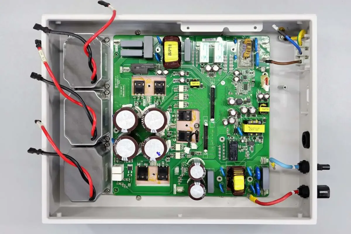
Solar inverters convert direct current (DC) from solar panels into alternating current (AC) for household or grid use. This process generates significant heat and electrical stress, making the choice of PCB material crucial. The right material ensures efficient heat dissipation, maintains signal integrity, and withstands environmental factors like humidity and temperature fluctuations. Poor material choices can lead to overheating, reduced efficiency, or even system failure, costing time and money. Let's dive into how advanced PCB materials address these challenges and enhance both performance and durability.
Key Requirements for PCB Materials in Solar Inverters
Before exploring specific materials, it's important to understand the demands placed on PCBs in solar inverters. These devices often operate in outdoor environments or confined spaces with limited airflow, so the PCB must meet several criteria:
- High Thermal Conductivity: Efficient heat dissipation prevents component damage and maintains performance. Materials with thermal conductivity above 1 W/mK are often preferred.
- High-Temperature Resistance: Solar inverters can experience temperatures exceeding 85°C, so materials must resist degradation at these levels.
- Electrical Insulation: Good dielectric properties prevent short circuits and ensure reliable operation under high voltage.
- Durability: Resistance to moisture, UV exposure, and mechanical stress ensures a long lifespan, often over 10-15 years for solar applications.
- Cost-Effectiveness: Balancing performance with affordability is key for large-scale production.
With these requirements in mind, let’s look at the most common and advanced PCB materials for solar inverters, focusing on how they meet these needs.
FR-4 PCB: The Standard Choice for Solar Inverters
FR-4 is one of the most widely used PCB materials across industries, including solar inverters. Made from woven fiberglass cloth with an epoxy resin binder, FR-4 offers a good balance of cost and performance. Its thermal conductivity is relatively low, around 0.3-0.4 W/mK, which may not be ideal for high-power inverters. However, it can handle temperatures up to 130°C with standard grades and higher with specialized versions.
For solar inverters with moderate power ratings (up to 5 kW), FR-4 works well due to its affordability and decent electrical insulation (dielectric strength of about 20 kV/mm). It’s also easy to manufacture, supporting complex multi-layer designs for control circuits in inverters. However, in high-temperature environments or for inverters exceeding 10 kW, FR-4 may struggle with heat dissipation, leading to potential delamination or reduced lifespan.
Best Use Case: FR-4 is ideal for small to medium solar inverters where cost is a priority, and operating temperatures remain below 100°C.
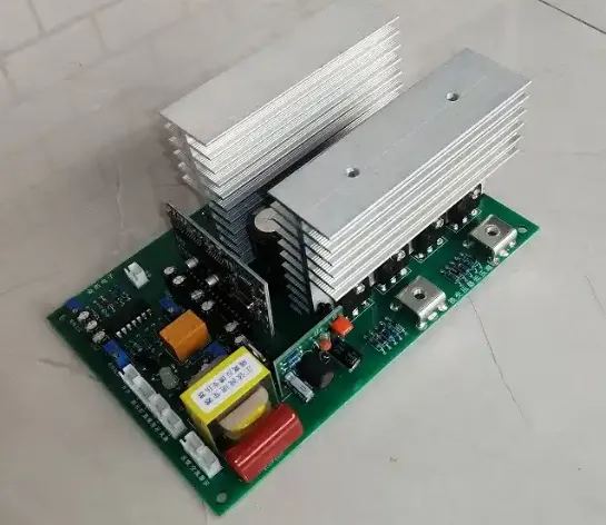
Metal Core PCB (MCPCB): Superior Thermal Management
For solar inverters operating at higher power levels or in hotter climates, metal core PCBs (MCPCBs) are a game-changer. MCPCBs feature a metal base layer, usually aluminum or copper, which provides excellent thermal conductivity—often in the range of 1-5 W/mK for aluminum and up to 400 W/mK for specialized copper-based designs. This metal layer acts as a heat sink, rapidly transferring heat away from critical components like power transistors and diodes.
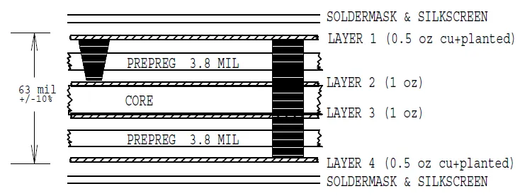
In solar inverters, where heat generation can exceed 100°C during peak operation, MCPCBs significantly reduce thermal stress. They also offer good mechanical strength, making them resistant to vibrations and physical wear in outdoor installations. A typical MCPCB structure includes a thin dielectric layer (about 0.1 mm thick) between the metal base and copper circuit layer, maintaining electrical insulation while allowing heat to pass through.
One trade-off is cost—MCPCBs are more expensive than FR-4 due to the materials and manufacturing process. Additionally, they are heavier, which might be a concern for portable or compact inverter designs. Despite this, their ability to extend component life by maintaining lower operating temperatures (often 20-30°C cooler than FR-4 setups) makes them a top choice for high-performance solar inverters.
Best Use Case: MCPCBs shine in high-power solar inverters (above 10 kW) or systems exposed to extreme heat, ensuring reliability and efficiency.
Ceramic PCB: High-Temperature Resistance and Efficiency
Ceramic PCBs are an advanced option for solar inverters where extreme conditions demand the highest performance. Made from materials like alumina (Al2O3) or aluminum nitride (AlN), ceramic PCBs offer outstanding thermal conductivity, ranging from 30 to 180 W/mK, far surpassing both FR-4 and most MCPCBs. They can withstand temperatures up to 350°C or more, making them ideal for inverters in harsh environments, such as desert regions with intense sunlight.
Beyond thermal performance, ceramic PCBs provide excellent electrical insulation and low thermal expansion, reducing the risk of cracking or warping over time. This durability is vital for solar inverters expected to operate for 15-20 years with minimal maintenance. For instance, aluminum nitride ceramic PCBs are often used in high-end inverters due to their ability to handle high voltage (up to 15 kV/mm dielectric strength) and dissipate heat efficiently.
The main drawback of ceramic PCBs is their high cost, often 5-10 times more expensive than FR-4, and their brittleness, which can lead to damage during handling or installation. They are also harder to manufacture, limiting design flexibility compared to other materials. However, for critical applications where failure is not an option, the investment in ceramic PCBs pays off through unmatched reliability.
Best Use Case: Ceramic PCBs are perfect for premium solar inverters in extreme climates or for systems requiring the highest efficiency and longevity.
Comparing PCB Thermal Conductivity Across Materials
Thermal conductivity is a critical factor in choosing PCB materials for solar inverters, as it directly impacts heat dissipation and system efficiency. Here's a quick comparison of the materials discussed:
- FR-4 PCB: 0.3-0.4 W/mK – Suitable for low to medium heat dissipation needs.
- Metal Core PCB (Aluminum): 1-5 W/mK – Excellent for moderate to high heat dissipation in larger inverters.
- Metal Core PCB (Copper-Based): Up to 400 W/mK in specialized designs – Ideal for extreme thermal management.
- Ceramic PCB (Alumina): 30-40 W/mK – Superior heat transfer for demanding applications.
- Ceramic PCB (Aluminum Nitride): 150-180 W/mK – Top-tier performance for critical systems.
Choosing the right material depends on your inverter’s power rating, operating environment, and budget. For example, a 3 kW residential inverter might perform well with FR-4, while a 50 kW commercial inverter in a hot climate would benefit from a metal core or ceramic PCB to manage heat effectively.
High-Temperature PCB Materials: Addressing Environmental Challenges
Solar inverters often face high-temperature environments, especially in outdoor setups where ambient temperatures can reach 50°C or more. High-temperature PCB materials are designed to resist thermal degradation, maintaining structural integrity and electrical performance. Both MCPCBs and ceramic PCBs fall into this category, but their approaches differ.
MCPCBs rely on their metal base to act as a heat sink, pulling heat away from components. This is particularly effective in inverters with high current flow, where heat generation is concentrated in specific areas. Ceramic PCBs, on the other hand, distribute heat more evenly due to their uniform material properties, preventing hotspots that could damage sensitive parts.
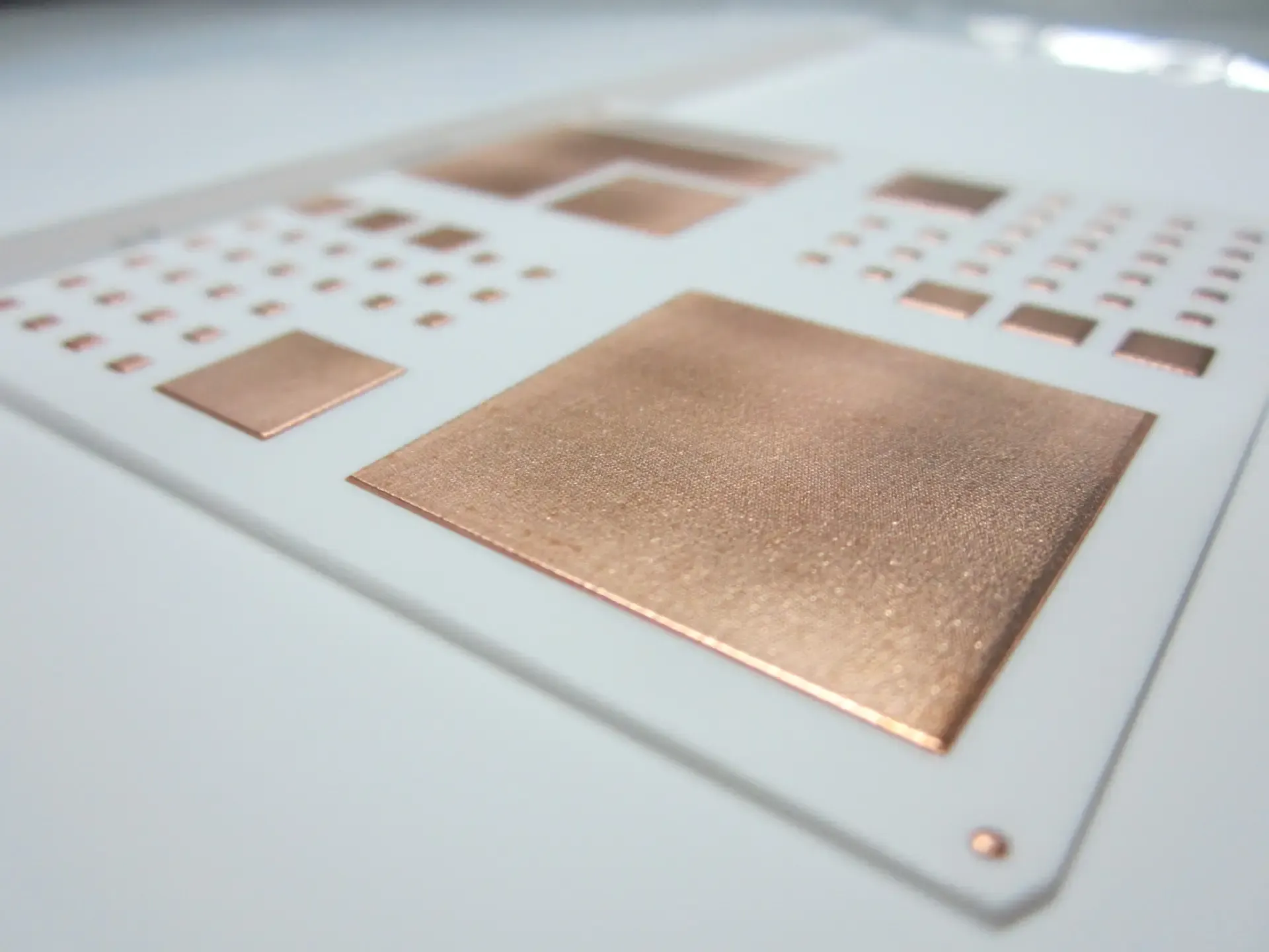
In addition to material choice, design considerations like thicker copper traces (2-3 oz/ft2) and strategic component placement can further enhance high-temperature performance. Using high-temperature solder and conformal coatings also protects the PCB from moisture and dust, common in outdoor solar installations.
How to Choose the Right PCB Material for Your Solar Inverter
Selecting the best PCB material for a solar inverter involves balancing performance needs with budget constraints. Here are some practical steps to guide your decision:
- Assess Power Requirements: Determine the inverter’s power output. Low-power systems (under 5 kW) can often use FR-4, while high-power systems (above 10 kW) may need MCPCB or ceramic.
- Evaluate Operating Environment: Consider ambient temperature, humidity, and exposure to elements. Hot or humid areas benefit from high-temperature materials like ceramic or MCPCB.
- Calculate Thermal Load: Estimate heat generation based on current and voltage levels. Choose a material with thermal conductivity that matches or exceeds your needs.
- Set a Budget: FR-4 is the most cost-effective, while ceramic is the priciest. Weigh the long-term benefits of durability against upfront costs.
- Consult with Experts: Work with PCB design and manufacturing teams to ensure compatibility with your inverter’s specifications.
By taking a systematic approach, you can ensure your solar inverter operates efficiently and reliably for years to come.
Future Trends in PCB Materials for Solar Inverters
As solar technology advances, so do the materials used in PCB manufacturing. Researchers are exploring hybrid materials that combine the benefits of metal and ceramic for even better thermal performance. Additionally, eco-friendly PCB materials with reduced environmental impact are gaining traction, aligning with the sustainability goals of the solar industry.
Another trend is the integration of advanced cooling technologies directly into PCB designs, such as embedded heat pipes or microchannels. These innovations could further enhance the performance of solar inverters, especially in compact, high-density systems where space for external cooling is limited.
Conclusion: Building Better Solar Inverters with Advanced PCB Materials
Choosing the right PCB materials for solar inverters is a critical step in ensuring optimal performance and durability. Whether you opt for the cost-effective FR-4 PCB, the thermally efficient metal core PCB, or the high-performance ceramic PCB, understanding your project’s specific needs is key. Factors like thermal conductivity, temperature resistance, and environmental conditions all play a role in determining the best fit.
At ALLPCB, we’re committed to helping engineers and designers create reliable, high-quality solar inverters with cutting-edge PCB solutions. By leveraging advanced materials and tailored designs, you can build systems that maximize energy efficiency and stand the test of time. Focus on the right material, and your solar inverter will deliver consistent power conversion for years, even in the toughest conditions.


