ALLPCB


Are you an engineer struggling with ATM PCB failures? Whether it's a malfunctioning card reader, a cash dispenser issue, or a complete system breakdown, diagnosing and repairing printed circuit boards (PCBs) in automated teller machines (ATMs) can be a daunting task. In this detailed guide, we’ll walk you through the essentials of ATM PCB fault diagnosis, highlight common ATM PCB failures, and provide practical PCB repair techniques, ATM PCB testing methods, and failure analysis for ATMs. Let’s dive into the world of ATM PCB troubleshooting to help you resolve issues efficiently and keep systems running smoothly.
Why ATM PCB Failures Matter
ATMs are critical machines in the financial sector, handling millions of transactions daily. A single PCB failure can disrupt operations, leading to downtime, frustrated customers, and revenue loss. PCBs in ATMs control everything from cash dispensing to user interface displays, making their reliability essential. Understanding how to diagnose and fix these issues not only saves time but also reduces maintenance costs. In this blog, we’ll break down the most frequent problems and equip you with the tools and knowledge to tackle them head-on.
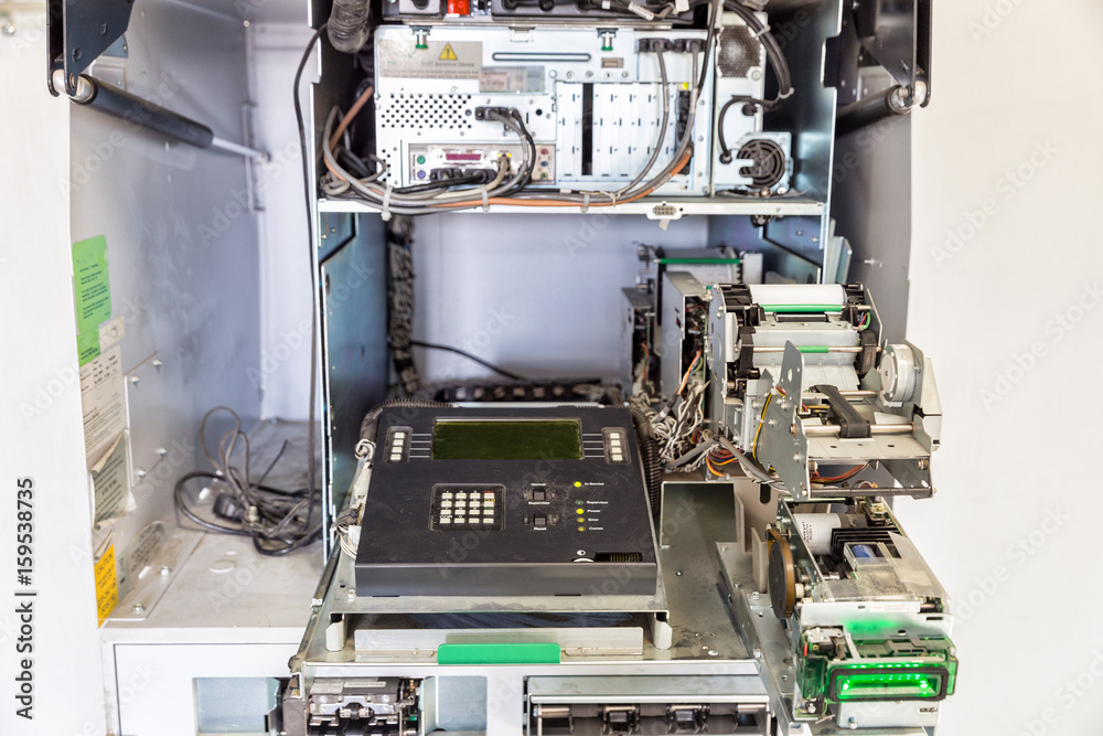
Understanding the Role of PCBs in ATMs
Before diving into troubleshooting, it’s important to understand the role of PCBs in ATMs. These boards are the backbone of the machine, managing critical functions such as:
- Processing user inputs through keypads and touchscreens.
- Controlling cash dispensers and deposit mechanisms.
- Managing communication with banking networks.
- Handling power distribution and sensor data.
A typical ATM may contain multiple PCBs, each dedicated to a specific function. For instance, the main control board oversees overall operations, while smaller boards handle card readers or receipt printers. When a failure occurs, pinpointing the faulty board is the first step in ATM PCB fault diagnosis.
Common ATM PCB Failures: What to Look For
ATM PCBs are exposed to harsh conditions, including temperature fluctuations, dust, and constant usage, which can lead to various failures. Below are some of the most common ATM PCB failures engineers encounter:
1. Power Supply Issues
Power-related problems often manifest as intermittent operation or complete shutdowns. A faulty voltage regulator or a blown capacitor on the PCB can cause unstable power delivery, leading to system crashes. For instance, if the input voltage drops below the required 12V or 24V (common in ATM systems), components may fail to operate.
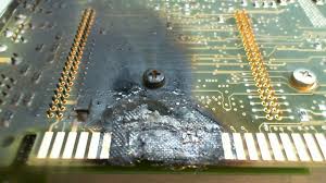
2. Component Burnout
Overheating or electrical surges can burn out components like resistors, diodes, or integrated circuits (ICs). Burnt components are often visible as blackened or melted spots on the PCB, and they typically result in specific module failures, such as a non-functional card reader.
3. Connection Failures
Loose or corroded connectors between PCBs and peripherals can disrupt signals. For example, a poor connection between the main board and the cash dispenser can prevent cash from being dispensed, even if the software signals the transaction as complete.
4. Signal Integrity Problems
Signal issues arise when traces on the PCB are damaged or when electromagnetic interference (EMI) affects communication. This can lead to errors in data transmission, with symptoms like incorrect transaction logs or frozen screens. Signal speeds in ATMs often operate at frequencies around 10-50 MHz, and any disruption can cause noticeable delays or failures.
5. Environmental Damage
Moisture, dust, and extreme temperatures can degrade PCB materials over time. Corrosion on solder joints or delamination of the board layers can lead to intermittent faults or total failure. ATMs in humid regions are particularly prone to such issues.
Step-by-Step Guide to ATM PCB Fault Diagnosis
Effective ATM PCB fault diagnosis requires a systematic approach. Follow these steps to identify and resolve issues with precision:
Step 1: Initial Observation
Start by observing the ATM’s behavior. Note any error codes displayed on the screen, unusual sounds, or non-responsive modules. For instance, if the cash dispenser fails to eject money but the screen shows a successful transaction, the issue likely lies with the dispenser’s control PCB.
Step 2: Visual Inspection
Power down the ATM and carefully remove the suspected PCB. Use a magnifying glass to inspect for physical damage, such as cracks, burns, or bulging capacitors. Check for loose wires or connectors that might be causing intermittent issues.
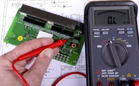
Step 3: Power and Voltage Testing
Use a multimeter to measure voltage levels at key points on the PCB. Ensure that the input voltage matches the specifications (e.g., 12V or 24V for most ATM boards). Test for continuity across power traces to rule out broken connections.
Step 4: Component Testing
Identify and test individual components like resistors, capacitors, and ICs. For example, a capacitor with a capacitance rating of 10μF should be tested to ensure it’s within tolerance. Replace any component that shows abnormal readings.
Step 5: Signal Analysis
Use an oscilloscope to analyze signal integrity if the issue involves data transmission. Check for noise or distortion in waveforms, especially if the ATM’s communication with the banking network is failing. Ensure signal frequencies remain within the expected range of 10-50 MHz.
ATM PCB Testing Methods for Accurate Results
Applying the right ATM PCB testing methods is crucial for confirming the root cause of a failure. Here are some proven techniques:
1. Continuity Testing
Use a multimeter to check for open or short circuits in the PCB traces. This method helps identify broken connections or unintended shorts that could disrupt operations.
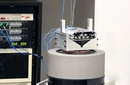
2. Thermal Imaging
A thermal camera can detect overheating components on the PCB. Hotspots often indicate failing parts, such as a voltage regulator dissipating excess heat due to a short circuit.
3. Functional Testing
After repairs, reassemble the PCB and test the ATM in a controlled environment. Simulate transactions to ensure all modules, like the card reader and cash dispenser, function correctly.
4. Automated Diagnostic Tools
Some ATMs come with built-in diagnostic software that logs errors and pinpoints faulty components. Use these logs to narrow down issues to specific PCBs or peripherals.
PCB Repair Techniques for ATM Boards
Once the fault is identified, applying effective PCB repair techniques can restore functionality. Here’s how to handle common repairs:
1. Soldering and Desoldering
For damaged or burnt components, carefully desolder the faulty part using a soldering iron and replace it with a matching component. Ensure the new component matches the original specifications, such as a 1kΩ resistor or a 5V regulator IC.
2. Trace Repair
If a trace is broken, use conductive epoxy or a fine wire to bridge the gap. Clean the area with isopropyl alcohol to prevent contamination before applying the repair material.
3. Connector Replacement
Corroded or loose connectors should be replaced with compatible parts. Secure them firmly to ensure reliable signal transmission between boards.
4. Protective Coating
After repairs, apply a conformal coating to protect the PCB from moisture and dust. This step is especially important for ATMs in outdoor or humid environments.
Failure Analysis for ATM PCBs: Preventing Future Issues
Conducting a thorough failure analysis for AT_tzinfo:4?
Conducting a thorough failure analysis for ATMs helps engineers understand why a PCB failed and how to prevent recurrence. Follow these steps:
1. Document the Failure
Record the symptoms, error codes, and environmental conditions at the time of failure. For example, note if the ATM was exposed to high humidity or a power surge.
2. Analyze Component Stress
Examine components for signs of overvoltage or overheating. For instance, if a capacitor rated for 16V failed under a 20V surge, consider installing a higher-rated component or adding surge protection.
3. Review Maintenance Logs
Check the ATM’s maintenance history for patterns. Frequent failures in the same module may indicate a design flaw or inadequate cooling.
4. Implement Preventive Measures
Based on your analysis, update maintenance schedules, improve environmental controls, or upgrade components to withstand harsher conditions.
Best Practices for Maintaining ATM PCBs
Prevention is better than repair. Adopt these best practices to minimize common ATM PCB failures:
- Regularly clean PCBs to remove dust and debris that can cause shorts.
- Monitor environmental conditions, keeping humidity below 60% and temperatures between 5°C and 35°C.
- Schedule routine inspections to catch early signs of wear, such as frayed cables or corroded connectors.
- Use surge protectors to safeguard against power spikes, especially in areas prone to electrical instability.
Tools Every Engineer Needs for ATM PCB Troubleshooting
Having the right tools makes ATM PCB fault diagnosis faster and more accurate. Essential tools include:
- Multimeter: For measuring voltage, current, and continuity.
- Oscilloscope: For analyzing signal integrity and detecting noise.
- Soldering Station: For replacing components and repairing traces.
- Thermal Camera: For identifying overheating components.
- Magnifying Glass or Microscope: For detailed visual inspections.
Conclusion: Mastering ATM PCB Troubleshooting
Troubleshooting ATM PCB failures doesn’t have to be overwhelming. By understanding common ATM PCB failures, following a structured approach to ATM PCB fault diagnosis, and using reliable ATM PCB testing methods, engineers can quickly identify and resolve issues. Combining effective PCB repair techniques with detailed failure analysis for ATMs ensures long-term reliability and minimizes downtime. With the right tools and preventive measures, you can keep ATMs running smoothly and maintain customer trust.
At ALLPCB, we’re committed to supporting engineers with high-quality PCB solutions and resources. Whether you’re dealing with a complex failure or looking to optimize your designs, our expertise is here to help you succeed in every project.