 ALLPCB


In the fast-evolving world of electronics, managing heat in printed circuit boards (PCBs) is a critical challenge. Overheating can lead to component failure, reduced performance, and shorter device lifespans. So, how can you ensure efficient PCB heat dissipation? One innovative solution is using buried resistors for better thermal management. In this blog, we’ll dive deep into how buried resistors help with thermal performance and offer practical tips for integrating them into your designs to optimize buried resistor heat transfer.
What Are Buried Resistors and Why Do They Matter for Thermal Management?
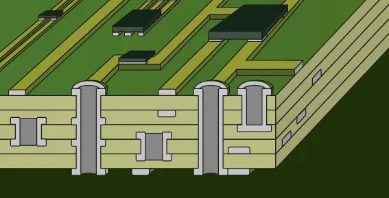
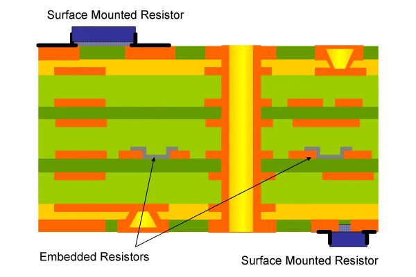
Buried resistors are resistive elements embedded within the internal layers of a PCB, rather than being placed on the surface. Unlike traditional surface-mounted resistors, these components are integrated into the board’s structure during the manufacturing process. This unique placement offers several advantages, especially when it comes to buried resistors thermal management.
Heat dissipation is a major concern in high-density PCB designs where components are packed tightly together. Buried resistors help by distributing heat more evenly across the internal layers of the board. Since they are not exposed to the surface, the heat they generate is less likely to affect nearby components directly. Instead, it spreads through the PCB’s material, reducing localized hotspots and improving overall thermal performance.
The Science Behind Buried Resistor Heat Transfer
To understand how buried resistors contribute to PCB heat dissipation, let’s break down the basics of heat transfer. Heat moves through three main mechanisms: conduction, convection, and radiation. In a PCB, conduction—where heat travels through the material—is the primary mode of heat transfer. The materials used in a PCB, such as copper traces and dielectric layers, play a big role in how effectively heat is managed.
Buried resistors, embedded within these layers, transfer heat directly into the surrounding board material. Copper, a common material in PCBs, has excellent thermal conductivity (around 400 W/m·K), allowing heat to spread quickly. By placing resistors inside the board, the heat they generate is conducted away from the surface, reducing the risk of overheating sensitive components. Studies suggest that using buried resistors can reduce surface temperatures by up to 10-15% in high-power designs compared to surface-mounted alternatives.
Additionally, the internal placement shields resistors from external airflow variations, ensuring more consistent buried resistor heat transfer. This makes them ideal for applications where stable thermal performance is critical, such as in automotive electronics or industrial control systems.
Benefits of Using Buried Resistors for PCB Heat Dissipation
Integrating buried resistors into your PCB design offers multiple benefits for thermal management. Here are some key advantages:
- Reduced Surface Heat: Since buried resistors are not on the PCB surface, they prevent direct heat buildup in areas where other components are mounted. This minimizes the risk of thermal interference.
- Space Efficiency: Embedding resistors inside the board frees up surface space for other components, allowing for more compact designs without sacrificing thermal performance.
- Improved Reliability: By distributing heat more evenly, buried resistors help maintain consistent operating temperatures, reducing thermal stress on components and extending the lifespan of the PCB.
- Better Signal Integrity: Buried resistors can also be used to control impedance (typically in the range of 50-100 ohms for high-speed signals), reducing signal noise while managing heat effectively.
How to Implement Buried Resistors in Your PCB Design
Using buried resistors for PCB heat dissipation requires careful planning during the design and manufacturing stages. Below are actionable steps to incorporate them effectively into your projects:
1. Choose the Right Materials
The thermal conductivity of your PCB materials directly impacts the effectiveness of buried resistor heat transfer. Opt for substrates with higher thermal conductivity, such as FR-4 with enhanced copper content or specialized materials like metal-core PCBs for high-power applications. These materials help dissipate heat more efficiently from buried components.
2. Optimize Resistor Placement
Place buried resistors in areas of the PCB where heat can be evenly distributed. Avoid clustering them near high-power components that already generate significant heat. Use thermal simulation software to model heat flow and identify the best locations for embedding resistors.
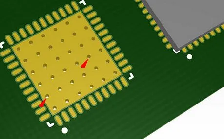
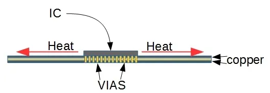
3. Use Thermal Vias for Enhanced Dissipation
Thermal vias are small holes filled with conductive material (usually copper) that transfer heat between PCB layers. Positioning thermal vias near buried resistors can improve heat dissipation by creating additional pathways for heat to escape to outer layers or heat sinks. For instance, a grid of thermal vias with a pitch of 1.2 mm can increase heat transfer by up to 20% in multilayer boards.
4. Balance Power Ratings
Ensure that the power ratings of buried resistors match the expected thermal load. Overloading a buried resistor can lead to excessive heat buildup within the PCB layers. As a rule of thumb, derate the resistor’s power rating by 25-30% to account for the confined environment inside the board.
Challenges and Limitations of Buried Resistors in Thermal Management
While buried resistors offer significant advantages for buried resistors thermal management, they are not without challenges. Being aware of these limitations can help you make informed decisions during the design process.
- Manufacturing Complexity: Embedding resistors within PCB layers requires advanced fabrication techniques, which can increase production costs and lead times. Precision in layer alignment and material selection is crucial to avoid defects.
- Limited Accessibility: Once buried, resistors cannot be easily replaced or adjusted. This makes prototyping and testing more challenging, as any changes may require a complete redesign of the board.
- Heat Trapping Risk: If not paired with proper heat dissipation methods like thermal vias or heat sinks, buried resistors can trap heat within the PCB, potentially leading to internal temperature spikes.
To mitigate these issues, collaborate closely with your PCB manufacturer to ensure that the design specifications align with their capabilities. Additionally, invest in thorough thermal analysis during the design phase to predict and address potential heat buildup.
Combining Buried Resistors with Other Heat Dissipation Techniques
For optimal PCB heat dissipation, buried resistors should be used alongside other proven thermal management strategies. Combining multiple techniques can address the limitations of any single method and enhance overall thermal performance. Here are a few complementary approaches:
1. Heat Sinks and Spreaders
Attach heat sinks or heat spreaders to the PCB surface to draw heat away from internal layers. These devices are particularly effective for high-power applications where buried resistors alone may not suffice. For example, a heat sink with a thermal resistance of 2°C/W can significantly lower operating temperatures.
2. Active Cooling Solutions
In designs with extreme heat generation, consider active cooling methods such as fans or liquid cooling systems. These solutions can work in tandem with buried resistors to maintain safe temperature levels, especially in compact, high-density boards.
3. Copper Planes for Heat Distribution
Incorporate large copper planes or pours in the PCB design to act as heat spreaders. These planes can connect to buried resistors through vias, distributing heat more evenly across the board and reducing localized hotspots.
Applications of Buried Resistors in Thermal Management
Buried resistors are particularly useful in industries and applications where thermal performance is non-negotiable. Some common use cases include:
- Automotive Electronics: In electric vehicles and engine control units, buried resistors help manage heat in compact, high-power systems exposed to harsh environments.
- Telecommunications: High-speed communication devices rely on buried resistors for impedance control and heat dissipation, ensuring signal integrity and reliability.
- Medical Devices: Compact medical equipment, such as wearable sensors, benefits from the space-saving and thermal management properties of buried resistors.
By tailoring the design to the specific thermal demands of these applications, engineers can achieve better performance and durability in their products.
Conclusion: Enhance Your PCB Design with Buried Resistors
Managing heat in modern PCB designs is more important than ever, and buried resistors offer a powerful solution for efficient PCB heat dissipation. By embedding resistors within the board’s layers, you can reduce surface heat, save space, and improve overall thermal performance. While there are challenges to consider, such as manufacturing complexity and heat trapping risks, these can be mitigated with careful planning and complementary techniques like thermal vias and heat sinks.
Whether you’re designing for automotive, telecommunications, or medical applications, integrating buried resistors into your PCB can make buried resistors thermal management easier and more effective. With the right materials, design strategies, and manufacturing support, you can create reliable, high-performing electronics that stand the test of time.
Start exploring the potential of buried resistor heat transfer in your next project and take your thermal management to the next level. With these insights, you’re well-equipped to tackle heat dissipation challenges and build better PCBs for any application.


